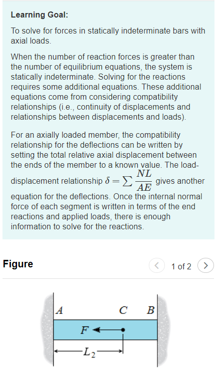
The square bar shown (Figure 1) is 70 mm thick and 5.4 m long and is fixed supported at both ends. A load directed leftward applied at point C, as shown, L2 = 3.3 m from the left end. The modulus of elasticity is E = 100 GPa .lf point C moves & = 0.13 mm to the left, what is the applied force?
Q: The bar shown in Fig. is subjected to a tensile load of 50 kN. Find the diameter of the middle…
A:
Q: Find the maximum load P that the column in Figure 2 can carry without buckling, in tons, E= 318…
A:
Q: Find out the crippling stress of the column if E=2×10⁵N/mm2 . Also, find out the shortest length of…
A: Given: Fix-hinge support do=40 mm=0.04 mdi=20 mm=0.02 mL=5 mE=2×10⁵ N/mm2σy=250 N/mm2 To determine:…
Q: AB and CD caps of the same material are tightly fitted on both ends of the 24 mm diameter AD steel…
A: Given: E = 200 GPa LAB = 48 mm LBC = 72 mm LCD = 48 mm DAB = 36 mm…
Q: Example 7 A steel bar of cross-sectional area 200 mm2 is loaded as shown in Fig. Find the change in…
A:
Q: A bar having two cross sectional areas is loaded by an axial force (P). Part AB and BC are circular…
A:
Q: 6) A steel rod with a cross-sectional area of 0.25 in? is stretched between two fixed points. The…
A:
Q: Ql: A bar ABCD shown in Figure (1) below consists of three sections: AB is of 42 mm diameter and 80…
A:
Q: A 1 m length bar of square cross section with side length 2cm, . is fully supported at one end and…
A: To find: The maximum force that bar can sustain elastically. Given: The length of the bar is l=1 m.…
Q: If a force of 300 kN is applied to the top of a circular steel bar with a diameter of 150mm and a…
A: Given: Now, Tensile force:
Q: 2 m, as shown in the figure below. Constructed, load P=5,000 N is given perpendicular to point C.…
A: Given that, Drawing the FBD of mechanism,
Q: Q2-B//a bar of 3m long and 25mm diameter at 70°C is gripped at ends and cooling to 30°C,the total…
A:
Q: 1. Axial bar loaded as shown in figure. Find the stress, strain and elongation at the tip of the…
A: Given, Length of the bar = L = 40 in Diameter of the bar = d = 1 in Load applied = P = 1000 lb…
Q: 2. The horizontal rigid bar AB is hinged (pinned) to a vertical wall at A and supported by two steel…
A:
Q: 4. A wood post 12 in. by 12 in. is braced by four steel angles. The wood post and the pieces of…
A: As per the bartleby policy we can solve only three subparts of any question. Given Data The length…
Q: 4. Compare between modulus of elasticity ( E) ( 180-220 GPa), and modulus of rigidity (G). for…
A: E=180-220 GPaμ=.27 to .3 for steel G=?E=2G1+μ
Q: hollow cast iron column of 150 mm external diameter and 100 mm internal diameter is 3.5 m long.…
A: Write the given values with the suitable variables. D=150 mm=0.150 md=100 mm=0.100 mL=2.5 mE=120…
Q: A bar ABCD shown in figure below consists of three sections: AB is of 42 mm diameter and 80 mm long,…
A:
Q: A vertical steel bar shown in figure Q1 is subiected to a compressive load of 75 kN. If the stress…
A:
Q: You are given a square rod of 6061-T6 aluminum (cross-section = 4mm X 4mm, length = 2.3m). The…
A:
Q: See the figure below. AD is a member with varying diameters. There are three axial loads applied at…
A: Given data: The magnitude of the force acting at the point B is; F1=10 lbs. The magnitude of the…
Q: Figure Q2 shows a shaft consists of Rods AB, BC and CD which made of Aluminium, Brass and Steel,…
A:
Q: The composite bar shown is firmly attached to unyielding supports. An axial load P=200 KN is applied…
A:
Q: Example: 5 A rigid bar AB, 9 m long, is supported by two vertical rods at its end and in a…
A:
Q: A rod is composed of three segments, as shown in the figure. Compute the stress induced in each…
A: According to the information we have a rod that is composed of three segments bronze, aluminum, and…
Q: The pin connected structure shown in the figure consists if a triangle shaped rigid bar, a cast iron…
A:
Q: 4. A steel bar of 40 mm x 40 mm square cross-section is subjected to an axial compressive load of…
A: Given, Cross sectional area = A = 40 mm x 40 mm = 1600 mm2 Axial compressive load = P = 200 kN = 200…
Q: A tensile load of 6 kN at 25 C was applied to a steel rod stretching between two rigid walls as…
A: Note:As per our guidelines we are supposed to answer only one question. Kindly repost other…
Q: 12. A composite bar made up of aluminium bar and steel bar, is firmly held between two unyielding…
A:
Q: he beam supports an 80 kg vertical mass applied at D. The beam is pinned to the wall at point A and…
A: Here, BC=15cm×15cm E=70GPa Load at D, FD=80×g=80×9.81N=784.8N Taking moment about point A. ∑MA=0…
Q: AB and CD caps of the same material are tightly fitted on both ends of the 24 mm diameter AD steel…
A:
Q: A tensile load of 6 kN at 25 C was applied to a steel rod stretching between two rigid walls as…
A: Given: F= 6 kN T=25°Cα=12.2 μm/(m°C)E=200 GPaσ=150 MPa
Q: The rigid plate ABC shown in figure 2, was positioned on top of two identical steel posts, and the…
A: Given Data For Steel E=200 GPaA=1600 mm2α=12×10-60Cσall comp=200 MPa For Aluminum E=73 GPaA=2400…
Q: A 1 m length bar of square cross section with side length 2cm, . is fully supported at one end and…
A:
Q: Question 2 A rod, which tapers uniformly from 40 mm diameter to 20 mm diameter in a length of 400 mm…
A:
Q: A steel bar of 30 mm * 30 mm square cross section is subjected to an axial compressive load of…
A: As per given A=30×30mm Load=300kn We have to determine contraction of bar
Q: A wire 4m long is stretched horizontally between points A and B 4m apart. A load W placed at the…
A: Given data Length of the Stretched wire = 4 mArea of cross-section of wire = 25 mm2Young's Modulus =…
Q: Question Two A steel flat of thickness 10 mm tapers uniformly from 60 mm at one end to 40 mm at…
A:
Q: A prismatic bar PQRST is subjected to axial loads as shown in the figure. The segments having…
A:
Q: To support a tensile load of 65 kN, a circular cross section and A metallic rod with a length of…
A: Given: The tensile load, P = 65 kN The length of rod, L = 0.32 m The stress in the bar, σ = 240 MPa…
Q: In the figure, member AB is used to support a load of 20kN at the free end, if the cable CD has a…
A: Answer: tensile stress in the cable = 62.37 MPaFor a step-by-step solution have a look through the…
Q: :Rigid bar ABCD is loaded and supported as shown in figure belov Bars (1) and (2) are unstressed…
A: Given that, E of bar 1 bronze, E1=100 GPa,E of bar 2 Aluminum, E2=70 GPa,Cross-section area of bar…
Q: The vertical rectanguler cross section column shown in Fig. Q4 is pinned at both ends. Assuming the…
A: Young's modulus is E=200 GPa. The yield strength is σy=250 MPa The dimension of the rectangular…
Q: What is the permanent set of the bar? b) What is the length of the unloaded bar? c) If the bar is…
A: The diagram must be supplemented with the problem but we have extracted the following diagram for…
Q: Three different materials, designed A, B and C are tested in tension using test specimens having…
A:
Q: A tensile load of 6 kN at 25 C was applied to a steel rod stretching between two rigid walls as…
A: Note:As per our guidelines we are supposed to answer only one question. Kindly repost other…
Q: Question 2: The cross-sectional area for the lattice rods in the figure is A=120 mm2, the modulus of…
A: given; AB=3m AC=4m
Q: A round bar of 10 mm diameter is made ofaluminum alloy 7075-T6 (see figure). When the baris…
A: Given Diameter, d = 10 mm Axial force = P 7075-T6 From Table H-2: E = 72 GPa Poisson ratio =…
Q: 1-A solid axial member which is made from three parts with different materials (sections 1,2, and 3)…
A: Section 1 Diameter, D1 = 30 mmSection 2 Diameter , D2 = 20 mmSection 3 Diameter, D3 = 25 mm
The question is attached. Thanks.
Trending now
This is a popular solution!
Step by step
Solved in 2 steps
- The scissors linkage is subjected to a force of P = 150 N as shown in the figure below. Thespring is unstretched at θ = 0◦. All links have equal length of 0.3 m. Using the principles of virtualwork, determine the equation in terms of θ, for the system to be in equilibrium. Neglect the massof the links. Find the numerical value of θ, by solving the equation that you have obtained,using a numerical method. Hint: You may look for a trial and error method, or Newton’s bisectionmethod, or Newton-Raphson method, etc. Please solve the questionLet's begin by determining the equilibrium position of a seesaw pivot. You and a friend play on a seesaw. Your mass is 90 kg, and your friend’s mass is 60 kg. The seesaw board is 3.0 mm long and has negligible mass. Where should the pivot be placed so that the seesaw will balance when you sit on the left end and your friend sits on the right end? a)Let's look at the same scenario we just worked through, but instead, the board now has a non-zero mass of 15 kg. Where should the pivot be placed for balance?Derive an expression to find the normal reactions at the front and rear wheels considering the stability of a vehicle on a slope of θ, to the horizontal. Also discuss, the limiting value for θ, if it is increased gradually (i) either the vehicle is about to overturn (ii) the vehicle is about to slide down the slope.
- INSTRUCTIONS: Solve the following problem by manually applying the finite element method, following these steps: Pre-processing: Geometry identification. Material properties identification. Load identification. Boundary condition identification. Development of the connectivity matrix for nodes and elements. Processing: Calculation of local stiffness matrices. Assembly of the global stiffness matrix. Assembly of the global force matrix (if required). Application of boundary conditions. Resolution of the system of equations. Derivation of the complete displacement vector (u). Post-processing: Reaction forces calculation. Stress analysis. Problem Statement: the truss nodes and elements (in parentheses) are already numbered. The areas (are in cm^2 ) are underlined. members are made of structural steel, modulus of elasticity is (E) of 20×10^6 N/cm^2 . the lengths are given in cm.a) Let R represent the reaction force at Support B. By releasing the beam at Support B and imposing a force R at Point B, the deflection of the beam consists of two parts,i.e. Part I- the deflection caused by MB ; Part II- the deflection caused by R Please treat R, w, h , L , E as variables in this step , the mathematical equation for the deflection at Point B caused by R ( Part II) can be written as (Hint : to input equation R2LQ2wh , you can type (R^2*L)/(Q^2*w*h) ) b) Using the provided data: cross-section width w = 20 mm, cross-section hight h = 93 mm, length of the beam L =3 m , beam material’s Young’s modulus Q =226 GPa, applied bending moment MB = 11 kN.m The value of the deflection at Point B caused by MB ( Part I) can be calculated as ......(in mm)5.31a shows a student pulling horizontally with a 100 N force on a rope that is attached to a wall. In 5.31b, two students in a tug-of-war pull on opposite ends of a rope with 100 N each. Is the tension in the second rope larger than, smaller than, or the same as that in the first?
- Her foot pivots as a single structure about a single pivot in her ankle. When she stands on tiptoe, her foot pivots about her ankle. As shown in the foot diagram and the free-body diagram below, the forces on one foot are an upward force on her toes from the floor, a downward force on her ankle from the lower leg bone (called the Tibia), and an upward force on the heel of her foot from her Achilles Tendon. Suppose a 61.3 kg woman stands on one foot, on tiptoe, with the sole of her foot making a 25.0 degree angle with the floor, and with the distances are as shown in the figure.The 300kn sphere is supported by a pull p and a 200kn weight passing over a frictionless pulley. If a=30°. Computer the value of p and tangent.A spring-loaded gun has a spring for which mNk/180=and is initially compressed bycm14. It fires a kg024.0projectile vertically. Find the maximum height above the initial position
- Course: Statics for Engineers Chapter: Ch5 ( Equilibrium of aRigid Body ) * A free-body Diagram must be included with the solution *The iillustration depicts a prototype design for the High-G Rover. It is made up of an arm that is attached to a shaft that is pinned to a disk. The aarm has a retractable shaft that extends and contracts to cause the disk to rotate. To make the computation easier, let us assumee that the arm does nott rotate A. If the arm's total length is L = 640mm, the distance from the centre of the disk to the shaft pin is r = 112mm, and the arm rotates clockwise at a constant angular velocity of 250.273 rpm. 1.) Would an increase in angular velocity increase point C's linear velocity relative to point A? If so, why or why not? a.) What is the linear velocity of point C with respect to point A if the angular position of the pin (between AB and BC) is 0.578 radians? b.) What is the distance between points A and C if the angular position of the pin (between AB and BC) is 0.578 radians? c.) What is the linear velocity of point C with respect to point A if the angular velocity is increased by 34.34…which equation is used if the system underdamped. can you pls share the whole eqn