QUESTIONS Complete questions I to 12. 1. Draw a single logic symbol for the 5-input OR gate you wired in this ex- periment. Label the inputs A, B, C, D, and E; label the output Y. 2. Draw a logic diagram of a 3-input OR gate using two 2-input OR gates. Label the inputs A, B, and C and the output Y. 3. When powering the IC in this experiment, the GND pin is connected to of the power supply. 3. the 4. A logical 0 put is a. Near GND voltage b. Near +5 V 5. A logical 1 on the truth table in this experiment means that input or out- the truth table in this experiment means that input or out- 4. 5. put is a. Near GND voltage b. Near +5 V 6. A truth table with two inputs has how many switch combinations? 7. A truth table with three inputs has how many switch combinations? 8. A truth table with five inputs has how many switch combinations? 9. The OR gate's unique output is a. occurs when all inputs are 10. The 7432 is described by the manufacturer as a quadruple 2-input OR gate from the 11. The logic circuit shown in Fig. 3-9(a) performs the 3-input 6. 7. 8. (0, 1), which only 9. (HIGH, LOW). 10. (CMOS, TTL) family of digital ICs. 11. (AND, OR) logic function. 12. The logic circuit drawn in Fig. 3-9(b) performs the 2-input 12. (NAND, OR) logic function. D- (a)
QUESTIONS Complete questions I to 12. 1. Draw a single logic symbol for the 5-input OR gate you wired in this ex- periment. Label the inputs A, B, C, D, and E; label the output Y. 2. Draw a logic diagram of a 3-input OR gate using two 2-input OR gates. Label the inputs A, B, and C and the output Y. 3. When powering the IC in this experiment, the GND pin is connected to of the power supply. 3. the 4. A logical 0 put is a. Near GND voltage b. Near +5 V 5. A logical 1 on the truth table in this experiment means that input or out- the truth table in this experiment means that input or out- 4. 5. put is a. Near GND voltage b. Near +5 V 6. A truth table with two inputs has how many switch combinations? 7. A truth table with three inputs has how many switch combinations? 8. A truth table with five inputs has how many switch combinations? 9. The OR gate's unique output is a. occurs when all inputs are 10. The 7432 is described by the manufacturer as a quadruple 2-input OR gate from the 11. The logic circuit shown in Fig. 3-9(a) performs the 3-input 6. 7. 8. (0, 1), which only 9. (HIGH, LOW). 10. (CMOS, TTL) family of digital ICs. 11. (AND, OR) logic function. 12. The logic circuit drawn in Fig. 3-9(b) performs the 2-input 12. (NAND, OR) logic function. D- (a)

Chapter22: Sequence Control
Section: Chapter Questions
Problem 6SQ: Draw a symbol for a solid-state logic element AND.

Related questions
Question
Transcribed Image Text:SUTH
NAME
DATE
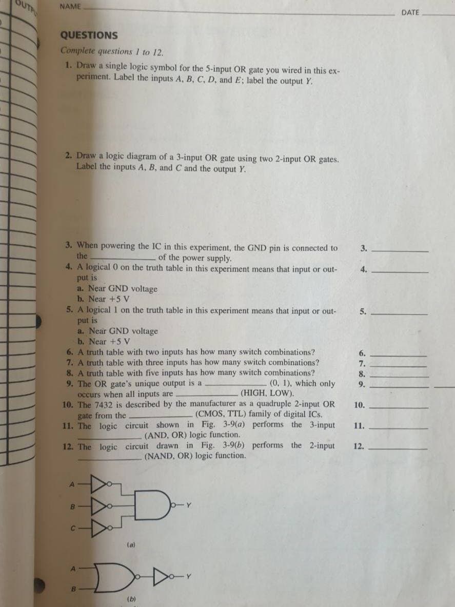
QUESTIONS
Complete questions 1 to 12.
1. Draw a single logic symbol for the 5-input OR gate you wired in this ex-
periment. Label the inputs A, B, C, D, and E; label the output Y.
2. Draw a logic diagram of a 3-input OR gate using two 2-input OR gates.
Label the inputs A, B, and C and the output Y.
3. When powering the IC in this experiment, the GND pin is connected to
of the power supply.
4. A logical 0 on the truth table in this experiment means that input or out-
3.
the
4.
put is
a. Near GND voltage
b. Near +5 V
5. A logical 1 on the truth table in this experiment means that input or out-
put is
a. Near GND voltage
b. Near +5 V
6. A truth table with two inputs has how many switch combinations?
7. A truth table with three inputs has how many switch combinations?
8. A truth table with five inputs has how many switch combinations?
9. The OR gate's unique output is a
occurs when all inputs are
10. The 7432 is described by the manufacturer as a quadruple 2-input OR
gate from the
11. The logic circuit shown in Fig. 3-9(a) performs the 3-input
5.
6.
7.
8.
(0, 1), which only
9.
(HIGH, LOW).
10.
(CMOS, TTL) family of digital ICs.
11.
(AND, OR) logic function.
12. The logic circuit drawn in Fig. 3-9(b) performs the 2-input
12.
(NAND, OR) logic function.
(a)
(b)
Expert Solution
This question has been solved!
Explore an expertly crafted, step-by-step solution for a thorough understanding of key concepts.

This is a popular solution!

Trending now
This is a popular solution!

Step by step
Solved in 4 steps with 3 images

Knowledge Booster


Learn more about
Need a deep-dive on the concept behind this application? Look no further. Learn more about this topic, electrical-engineering and related others by exploring similar questions and additional content below.Recommended textbooks for you