Refer to print PR 23-2. The sequence of operations for this print is given below. Answer the questions following the sequence of operations Sequence of operations Description: This is a system to control a 90-ton hydraulic, explosive-compaction press. The press ram descends at a controlled rate, slowly compacting the explosive charge to avoid detonation due to a sudden shock. 1. The cycle is started by energizing solenoid A, which shifts control valve (3) and supplies pressure to the head end of the hydraulic cylinder (7). This operates the ram. 2. The cylinder (7) extends at a slow rate controlled by the fluid in the rod end of the cylinder, which is vented through the flow control valve (5). 3. When the cylinder is fully extended and the pressing pressure is reached, the press ure switch (6) de-energizes solenoid A and energizes solenoid B. This shifts control valve (3) to retract the cylinder (7). Control valve (5) has an integral check valve that permits the free flow of fluid in the opposite direction, causing cylinder (7) to rapidly retract. A The retraction of cylinder (7) actuates the limit switch (8), which de-energizes solenoid B. Control valve (3) returns to the neutral position. This completes the cycle. This circuit has safety features. On power outage, both solenoid A and B are de-energized. This allows valve (3) to return to electrical the center position, thus stopping ram travel. Also, valve (4) provides low pressure relief on the ram upstroke and valve (2) provides high pressure relief on ram downstroke. Questions 8. What completes the cycle? 9. What happens in the event of electrical power outage? 10. Give the function of valves (2) and (4). SNIPIISIN APPROVED DATE DESCRIPTION PLAS COMPONENT LIST 1) UNIDIRECTIONAL, FIXED- DISPLACEMENT HYDRAULIC PUMP AND MOTOR. 2) HIGH-PRESSURE RELIEF VALVE 3) 4-WAY, 3-POSITION, BLOCKED- CENTER, DOUBLE SOLENOID-ACTUATED, MAINTAINED- CONTACT, SPRING-CENTERED VALVE. 4) LOW-PRESSURE RELIEF VALVE. 5) FLOW CONTROL VALVE, ADJUSTABLE AND PRESSURE COMPENSATED WITH BYPASS. Sol. A Sol. B 6) PRESSURE SWITCH УХI 7 DOUBLE-ACTING HYDRAULIC CYLINDER. 8) LIMIT SWITCH TEM M HEAT TREAT FINISH MATERIAL STOCK SIZE ON NO. TALLEY INDUSTRIES MESA, ARIZONA MANUFACTURING ENGRG DEPT ENGRG CHANGE TOOL NAME 90 TON HYDRAULIC PRESS SCHEMATIC ENGRG PART NAME 90 TON COMPACTION PRESS UNLESS OTHERWISE NOTED R.K. WALKER 8/28 G.A.Schneider 8/28 NMRA TOLERANCES ON: ANGLES 1 CHECKED MACHINED DIA ON A COMMON CENTERLINE CONCENTRIC WITHIN 005 T.I.R NORMALITY AND PARALLELISM OF MACHINED SURFACES .002 PER INCH TO A MAX. OF .010 FOR A SINGLE SURFACE REMOVE BURRS AND SHARP EDGES .030 MAX ZONE APPROVED OF 1 SCCALE SHEET ENGRG PART NO. SIZE CODE IDENT, NO TOOL DRAWING N0 8568321 ZNE A 12116 449 Unit 23 Instrumentation and Control Drawings 00 669 TO CN DU CH Print supplied by Talley Industrie PR 23-2. 90 Ton Hydraulic Press Schematic Copyright Goodheart-Willcox Co., Inc.
Refer to print PR 23-2. The sequence of operations for this print is given below. Answer the questions following the sequence of operations Sequence of operations Description: This is a system to control a 90-ton hydraulic, explosive-compaction press. The press ram descends at a controlled rate, slowly compacting the explosive charge to avoid detonation due to a sudden shock. 1. The cycle is started by energizing solenoid A, which shifts control valve (3) and supplies pressure to the head end of the hydraulic cylinder (7). This operates the ram. 2. The cylinder (7) extends at a slow rate controlled by the fluid in the rod end of the cylinder, which is vented through the flow control valve (5). 3. When the cylinder is fully extended and the pressing pressure is reached, the press ure switch (6) de-energizes solenoid A and energizes solenoid B. This shifts control valve (3) to retract the cylinder (7). Control valve (5) has an integral check valve that permits the free flow of fluid in the opposite direction, causing cylinder (7) to rapidly retract. A The retraction of cylinder (7) actuates the limit switch (8), which de-energizes solenoid B. Control valve (3) returns to the neutral position. This completes the cycle. This circuit has safety features. On power outage, both solenoid A and B are de-energized. This allows valve (3) to return to electrical the center position, thus stopping ram travel. Also, valve (4) provides low pressure relief on the ram upstroke and valve (2) provides high pressure relief on ram downstroke. Questions 8. What completes the cycle? 9. What happens in the event of electrical power outage? 10. Give the function of valves (2) and (4). SNIPIISIN APPROVED DATE DESCRIPTION PLAS COMPONENT LIST 1) UNIDIRECTIONAL, FIXED- DISPLACEMENT HYDRAULIC PUMP AND MOTOR. 2) HIGH-PRESSURE RELIEF VALVE 3) 4-WAY, 3-POSITION, BLOCKED- CENTER, DOUBLE SOLENOID-ACTUATED, MAINTAINED- CONTACT, SPRING-CENTERED VALVE. 4) LOW-PRESSURE RELIEF VALVE. 5) FLOW CONTROL VALVE, ADJUSTABLE AND PRESSURE COMPENSATED WITH BYPASS. Sol. A Sol. B 6) PRESSURE SWITCH УХI 7 DOUBLE-ACTING HYDRAULIC CYLINDER. 8) LIMIT SWITCH TEM M HEAT TREAT FINISH MATERIAL STOCK SIZE ON NO. TALLEY INDUSTRIES MESA, ARIZONA MANUFACTURING ENGRG DEPT ENGRG CHANGE TOOL NAME 90 TON HYDRAULIC PRESS SCHEMATIC ENGRG PART NAME 90 TON COMPACTION PRESS UNLESS OTHERWISE NOTED R.K. WALKER 8/28 G.A.Schneider 8/28 NMRA TOLERANCES ON: ANGLES 1 CHECKED MACHINED DIA ON A COMMON CENTERLINE CONCENTRIC WITHIN 005 T.I.R NORMALITY AND PARALLELISM OF MACHINED SURFACES .002 PER INCH TO A MAX. OF .010 FOR A SINGLE SURFACE REMOVE BURRS AND SHARP EDGES .030 MAX ZONE APPROVED OF 1 SCCALE SHEET ENGRG PART NO. SIZE CODE IDENT, NO TOOL DRAWING N0 8568321 ZNE A 12116 449 Unit 23 Instrumentation and Control Drawings 00 669 TO CN DU CH Print supplied by Talley Industrie PR 23-2. 90 Ton Hydraulic Press Schematic Copyright Goodheart-Willcox Co., Inc.

Precision Machining Technology (MindTap Course List)
2nd Edition
ISBN:9781285444543
Author:Peter J. Hoffman, Eric S. Hopewell, Brian Janes
Publisher:Peter J. Hoffman, Eric S. Hopewell, Brian Janes
Chapter8: Computer Numerical Control
Section8.6: Cnc Milling: Programming
Problem 7RQ: If during the last operation on a part, a G1 code command is programmed but no F-value is given in...

Related questions

Question
I need parts 7, 8, and 9, answered pertaining to the print and instructions.
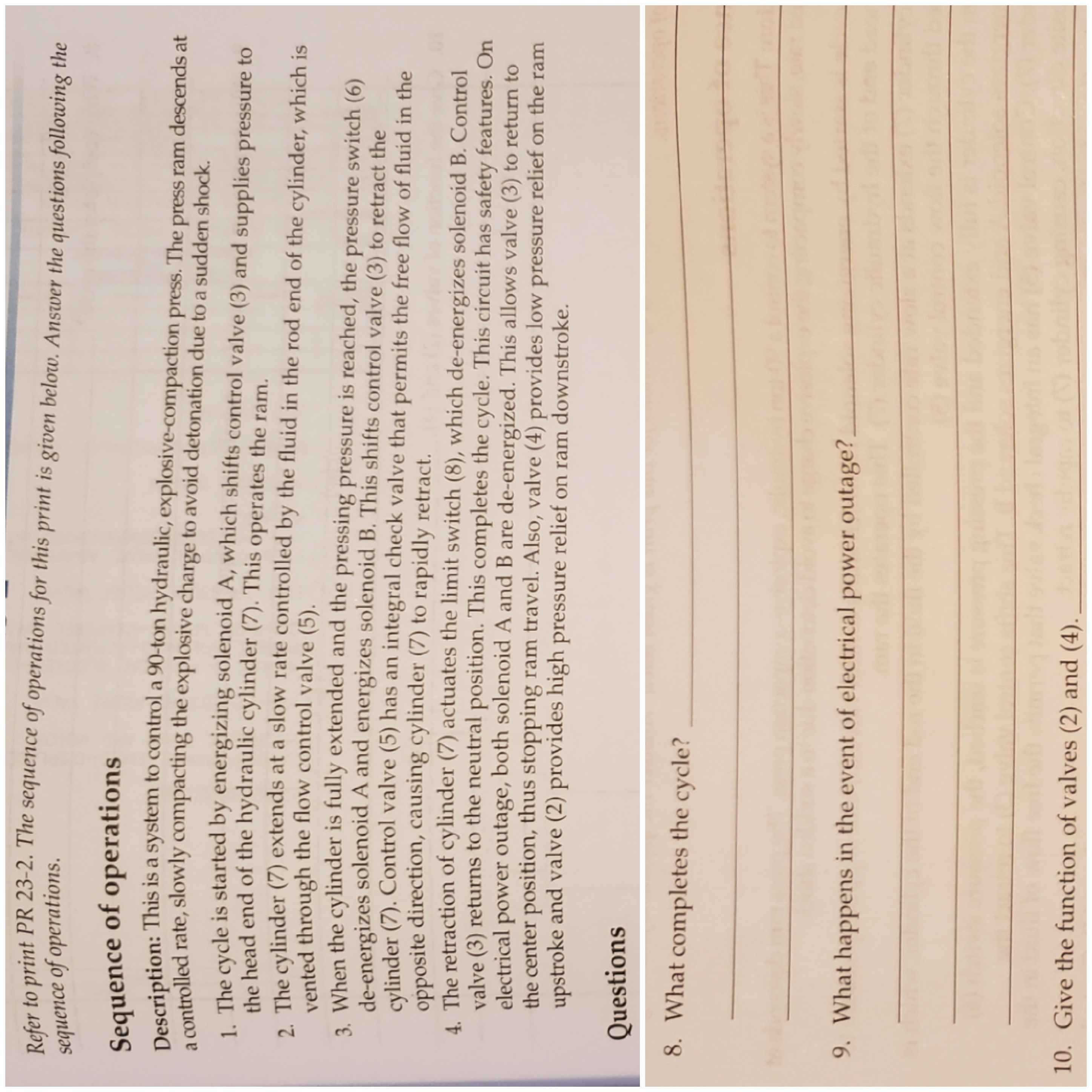
Transcribed Image Text:Refer to print PR 23-2. The sequence of operations for this print is given below. Answer the questions following the
sequence of operations
Sequence of operations
Description: This is a system to control a 90-ton hydraulic, explosive-compaction press. The press ram descends at
a controlled rate, slowly compacting the explosive charge to avoid detonation due to a sudden shock.
1. The cycle is started by energizing solenoid A, which shifts control valve (3) and supplies pressure to
the head end of the hydraulic cylinder (7). This operates the ram.
2. The cylinder (7) extends at a slow rate controlled by the fluid in the rod end of the cylinder, which is
vented through the flow control valve (5).
3. When the cylinder is fully extended and the pressing pressure is reached, the press ure switch (6)
de-energizes solenoid A and energizes solenoid B. This shifts control valve (3) to retract the
cylinder (7). Control valve (5) has an integral check valve that permits the free flow of fluid in the
opposite direction, causing cylinder (7) to rapidly retract.
A The retraction of cylinder (7) actuates the limit switch (8), which de-energizes solenoid B. Control
valve (3) returns to the neutral position. This completes the cycle. This circuit has safety features. On
power outage, both solenoid A and B are de-energized. This allows valve (3) to return to
electrical
the center position, thus stopping ram travel. Also, valve (4) provides low pressure relief on the ram
upstroke and valve (2) provides high pressure relief on ram downstroke.
Questions
8. What completes the cycle?
9. What happens in the event of electrical power outage?
10. Give the function of valves (2) and (4).
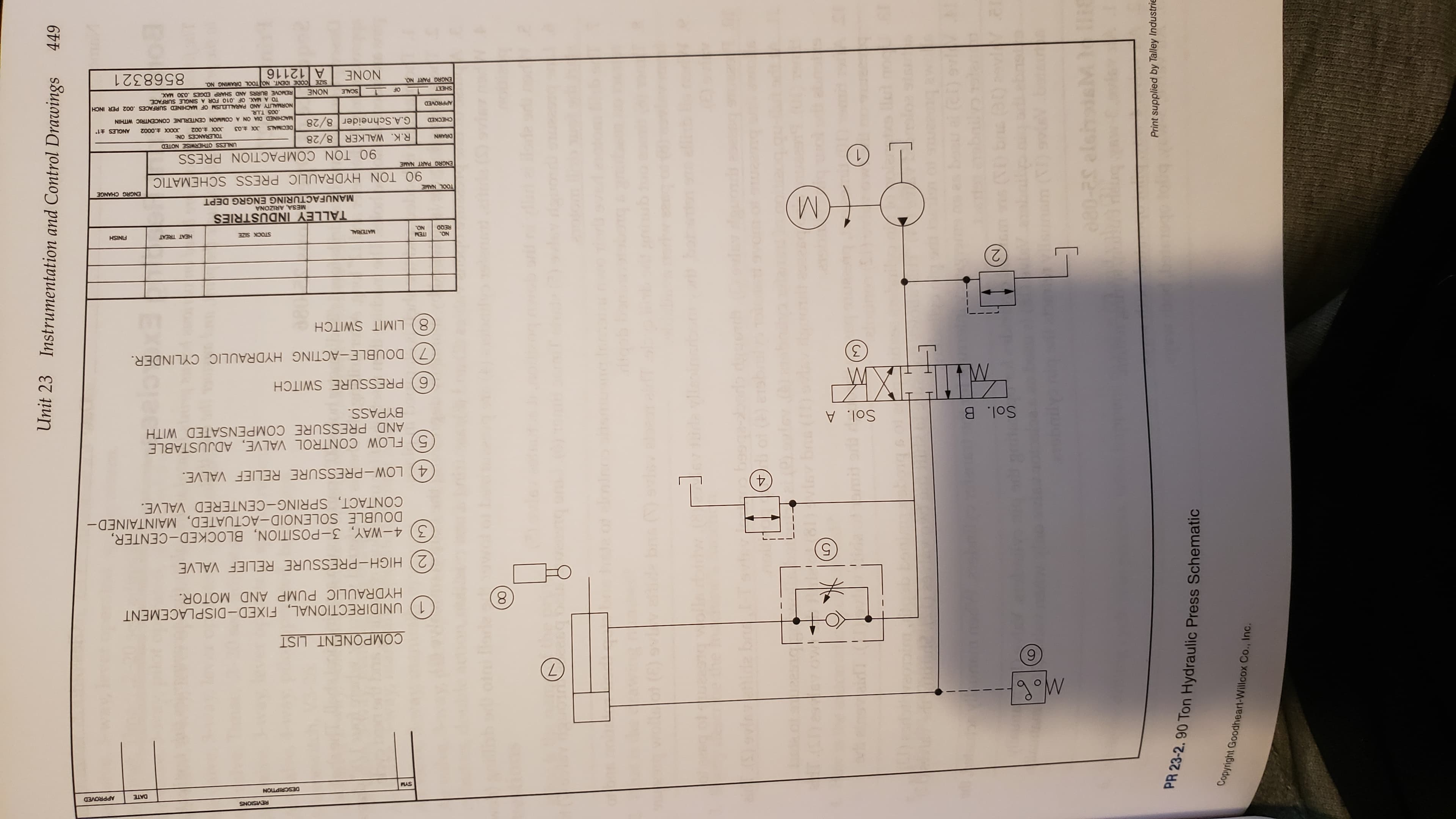
Transcribed Image Text:SNIPIISIN
APPROVED
DATE
DESCRIPTION
PLAS
COMPONENT LIST
1) UNIDIRECTIONAL, FIXED- DISPLACEMENT
HYDRAULIC PUMP AND MOTOR.
2) HIGH-PRESSURE RELIEF VALVE
3) 4-WAY, 3-POSITION, BLOCKED- CENTER,
DOUBLE SOLENOID-ACTUATED, MAINTAINED-
CONTACT, SPRING-CENTERED VALVE.
4) LOW-PRESSURE RELIEF VALVE.
5) FLOW CONTROL VALVE, ADJUSTABLE
AND PRESSURE COMPENSATED WITH
BYPASS.
Sol. A
Sol. B
6) PRESSURE SWITCH
УХI
7 DOUBLE-ACTING HYDRAULIC CYLINDER.
8) LIMIT SWITCH
TEM
M
HEAT TREAT
FINISH
MATERIAL
STOCK SIZE
ON
NO.
TALLEY INDUSTRIES
MESA, ARIZONA
MANUFACTURING ENGRG DEPT
ENGRG CHANGE
TOOL NAME
90 TON HYDRAULIC PRESS SCHEMATIC
ENGRG PART NAME
90 TON COMPACTION PRESS
UNLESS OTHERWISE NOTED
R.K. WALKER 8/28
G.A.Schneider 8/28
NMRA
TOLERANCES ON:
ANGLES 1
CHECKED
MACHINED DIA ON A COMMON CENTERLINE CONCENTRIC WITHIN
005 T.I.R
NORMALITY AND PARALLELISM OF MACHINED SURFACES .002 PER INCH
TO A MAX. OF .010 FOR A SINGLE SURFACE
REMOVE BURRS AND SHARP EDGES .030 MAX
ZONE
APPROVED
OF 1 SCCALE
SHEET
ENGRG PART NO.
SIZE CODE IDENT, NO TOOL DRAWING N0
8568321
ZNE
A 12116
449
Unit 23 Instrumentation and Control Drawings
00
669
TO
CN
DU CH
Print supplied by Talley Industrie
PR 23-2. 90 Ton Hydraulic Press Schematic
Copyright Goodheart-Willcox Co., Inc.
Expert Solution
Step 1
Hello. You have asked to solve question 7, 8 and 9 but, question 7 is not provided in the given image. Hence, we have solved the other two. Thank You.
Step 2
(8). The cycle is completed by the return of control valve (3) to the neutral position when solenoid B is de-energized due to the activation of limit switch (8) when the cylinder (7) retracts.

Step by step
Solved in 3 steps

Knowledge Booster


Learn more about
Need a deep-dive on the concept behind this application? Look no further. Learn more about this topic, mechanical-engineering and related others by exploring similar questions and additional content below.Recommended textbooks for you
Precision Machining Technology (MindTap Course Li…
Mechanical Engineering
ISBN:
9781285444543
Author:
Peter J. Hoffman, Eric S. Hopewell, Brian Janes
Publisher:
Cengage Learning
Precision Machining Technology (MindTap Course Li…
Mechanical Engineering
ISBN:
9781285444543
Author:
Peter J. Hoffman, Eric S. Hopewell, Brian Janes
Publisher:
Cengage Learning