Refer to print PR 23-1. The sequence of operations for this print is given below. Answer the questions following the sequence of operations. Sequence of operations onerator actuates the two push-button valves (1) and (2) until the weight starts to descend. lir passes through valves (1) and (2) to the time delay valve (3) and the pilot of valve (5). The four-way valve (5) is shifted, venting the head end of cylinder (4) and pressurizing the rod end. 4. The weight of the ram descends. The speed of descent is controlled by the exhaust control (7). The time delay valve (3) continues to time until the preset interval has passed. - The time delay valve (3) vents air pressure from the line between valve (2) and the pilot of valve (5). . With the pilot vented, the spring return of valve (5) shifts the valve to its normal position. O The rod end of cylinder (4) is vented and the head end is pressurized. 10. The weight ascends. 11. The speed of ascent is controlled by the exhaust control (6). Questions 8. What causes cylinder (4) to reverse? 9. What does the center line around valve (3) indicate? What component(s) are included? 10. Why is it not necessary to hold valves (1) and (2) down during the entire sequence? Unit 23 Instrumentation and Control Drawings 445 rch yPrint Ex 3) EXHAUST 2) MAN MAN Segu 4 AIR 9. (7) CLIPPARD MJV-2 12) 2-WAY PUSH-BUTTON VALVE 3) TIMAC AIR TIME DELAY VALVE TIMING RANGE .2-20 SECONDS MAC VAKVES INC. MODEL 71A-2-2 Queie AIRMATIC VALVE INC. 4) AIR CYLINDER MILLER FLUID POWER CO. MODEL 504, 1/4 NPT (5) 4-WAY 5-PORT SPRING RETURN VALVE LUB. 9. AIRMATIC VALVE INC. OR VERSA PRODUCTS CO. 67) EXHAUST CONTROL 8) SHUT OFF VALVE 9) FILTER-REGULATOR-LUBRICATOR COMBINATION WITH PRESSURE GAUGE. NORGREN FILT. PHOENIX PHOENIX, ARIZONA UNIDYNAMICS 8. A DIVISION OF UMC INDUSTRIES, INC. TOOL NAME PNEUMATIC CIRCUIT FOR DEAD WEIGHT PRESS SIZE CODE IDENT NO. DWG (TOOL) NO. 20-837 B 12079 Print supplied by Unidynar PR 23-1. Pneumatic Circuit for Dead Weight Press. Copyright Goodheart-Willcox Co., Inc. B.
Refer to print PR 23-1. The sequence of operations for this print is given below. Answer the questions following the sequence of operations. Sequence of operations onerator actuates the two push-button valves (1) and (2) until the weight starts to descend. lir passes through valves (1) and (2) to the time delay valve (3) and the pilot of valve (5). The four-way valve (5) is shifted, venting the head end of cylinder (4) and pressurizing the rod end. 4. The weight of the ram descends. The speed of descent is controlled by the exhaust control (7). The time delay valve (3) continues to time until the preset interval has passed. - The time delay valve (3) vents air pressure from the line between valve (2) and the pilot of valve (5). . With the pilot vented, the spring return of valve (5) shifts the valve to its normal position. O The rod end of cylinder (4) is vented and the head end is pressurized. 10. The weight ascends. 11. The speed of ascent is controlled by the exhaust control (6). Questions 8. What causes cylinder (4) to reverse? 9. What does the center line around valve (3) indicate? What component(s) are included? 10. Why is it not necessary to hold valves (1) and (2) down during the entire sequence? Unit 23 Instrumentation and Control Drawings 445 rch yPrint Ex 3) EXHAUST 2) MAN MAN Segu 4 AIR 9. (7) CLIPPARD MJV-2 12) 2-WAY PUSH-BUTTON VALVE 3) TIMAC AIR TIME DELAY VALVE TIMING RANGE .2-20 SECONDS MAC VAKVES INC. MODEL 71A-2-2 Queie AIRMATIC VALVE INC. 4) AIR CYLINDER MILLER FLUID POWER CO. MODEL 504, 1/4 NPT (5) 4-WAY 5-PORT SPRING RETURN VALVE LUB. 9. AIRMATIC VALVE INC. OR VERSA PRODUCTS CO. 67) EXHAUST CONTROL 8) SHUT OFF VALVE 9) FILTER-REGULATOR-LUBRICATOR COMBINATION WITH PRESSURE GAUGE. NORGREN FILT. PHOENIX PHOENIX, ARIZONA UNIDYNAMICS 8. A DIVISION OF UMC INDUSTRIES, INC. TOOL NAME PNEUMATIC CIRCUIT FOR DEAD WEIGHT PRESS SIZE CODE IDENT NO. DWG (TOOL) NO. 20-837 B 12079 Print supplied by Unidynar PR 23-1. Pneumatic Circuit for Dead Weight Press. Copyright Goodheart-Willcox Co., Inc. B.

Precision Machining Technology (MindTap Course List)
2nd Edition
ISBN:9781285444543
Author:Peter J. Hoffman, Eric S. Hopewell, Brian Janes
Publisher:Peter J. Hoffman, Eric S. Hopewell, Brian Janes
Chapter8: Computer Numerical Control
Section8.6: Cnc Milling: Programming
Problem 9RQ: Write two blocks of code that could be used to start the spindle in a clockwise direction at 2200...

Related questions

Question
I need problem 8 answered pertaining to the print and sequence of operations that is both provided.
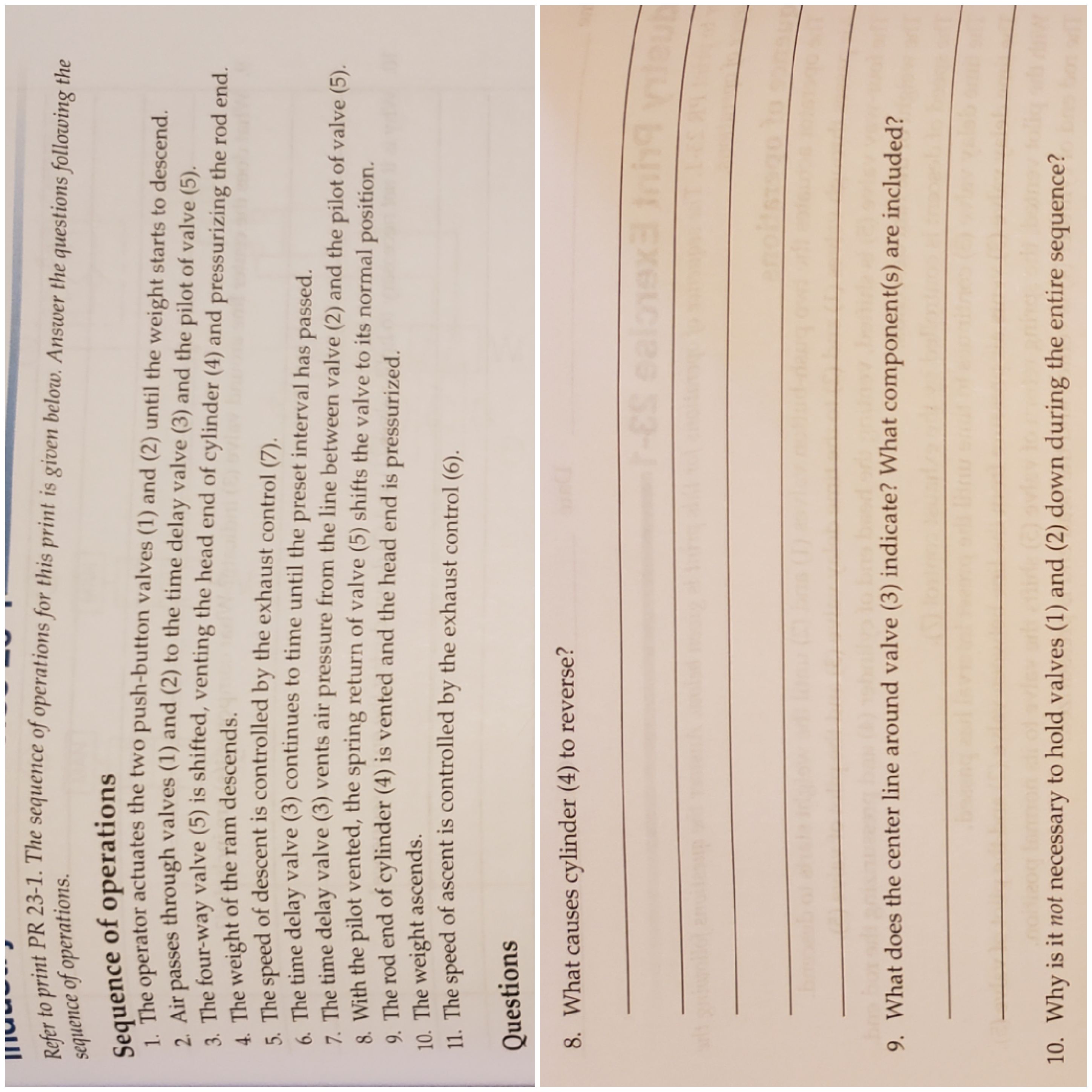
Transcribed Image Text:Refer to print PR 23-1. The sequence of operations for this print is given below. Answer the questions following the
sequence of operations.
Sequence of operations
onerator actuates the two push-button valves (1) and (2) until the weight starts to descend.
lir passes through valves (1) and (2) to the time delay valve (3) and the pilot of valve (5).
The four-way valve (5) is shifted, venting the head end of cylinder (4) and pressurizing the rod end.
4. The weight of the ram descends.
The speed of descent is controlled by the exhaust control (7).
The time delay valve (3) continues to time until the preset interval has passed.
- The time delay valve (3) vents air pressure from the line between valve (2) and the pilot of valve (5).
. With the pilot vented, the spring return of valve (5) shifts the valve to its normal position.
O The rod end of cylinder (4) is vented and the head end is pressurized.
10. The weight ascends.
11. The speed of ascent is controlled by the exhaust control (6).
Questions
8. What causes cylinder (4) to reverse?
9. What does the center line around valve (3) indicate? What component(s) are included?
10. Why is it not necessary to hold valves (1) and (2) down during the entire sequence?
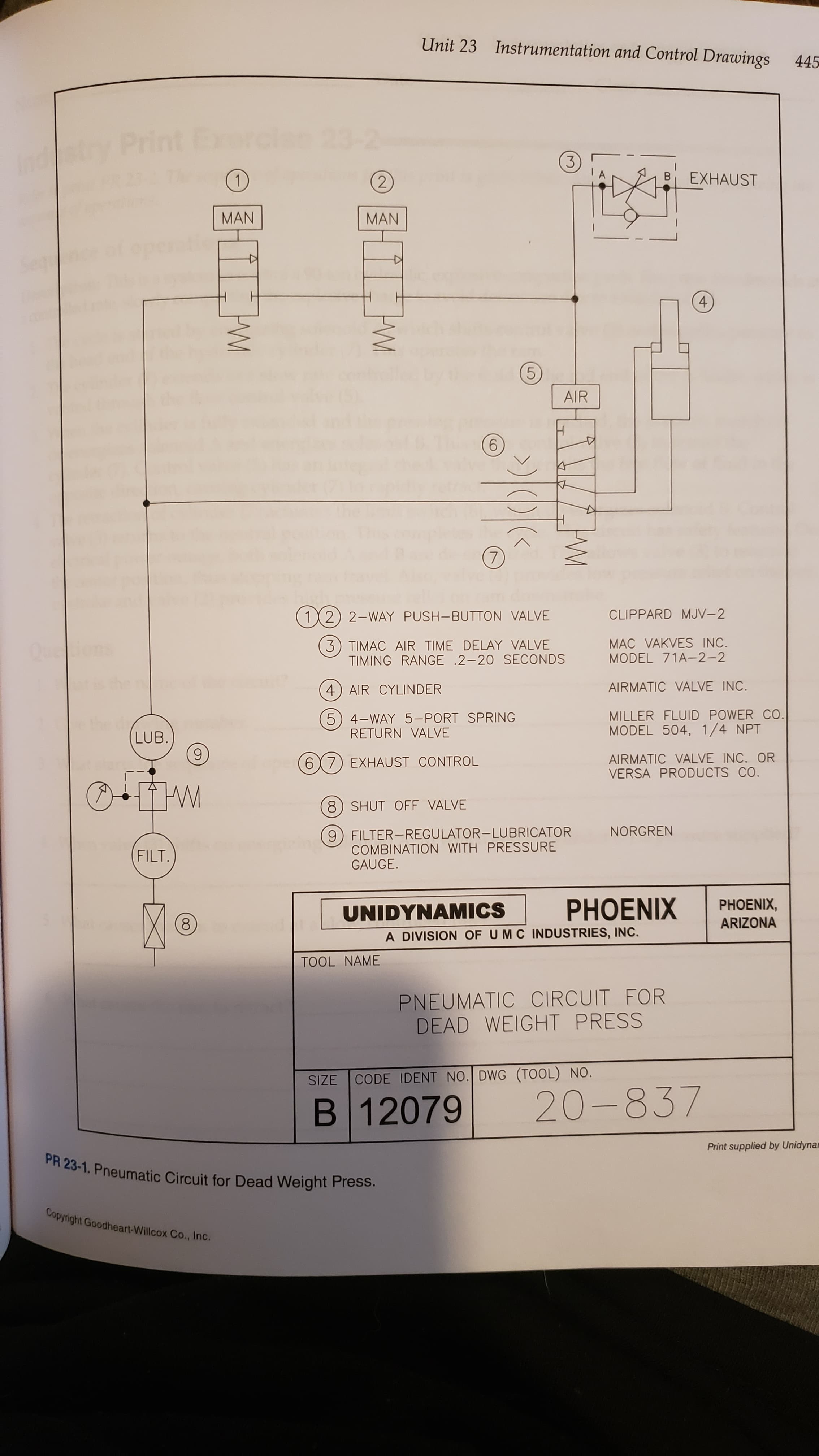
Transcribed Image Text:Unit 23
Instrumentation and Control Drawings
445
rch
yPrint Ex
3)
EXHAUST
2)
MAN
MAN
Segu
4
AIR
9.
(7)
CLIPPARD MJV-2
12) 2-WAY PUSH-BUTTON VALVE
3) TIMAC AIR TIME DELAY VALVE
TIMING RANGE .2-20 SECONDS
MAC VAKVES INC.
MODEL 71A-2-2
Queie
AIRMATIC VALVE INC.
4) AIR CYLINDER
MILLER FLUID POWER CO.
MODEL 504, 1/4 NPT
(5) 4-WAY 5-PORT SPRING
RETURN VALVE
LUB.
9.
AIRMATIC VALVE INC. OR
VERSA PRODUCTS CO.
67) EXHAUST CONTROL
8) SHUT OFF VALVE
9) FILTER-REGULATOR-LUBRICATOR
COMBINATION WITH PRESSURE
GAUGE.
NORGREN
FILT.
PHOENIX
PHOENIX,
ARIZONA
UNIDYNAMICS
8.
A DIVISION OF UMC INDUSTRIES, INC.
TOOL NAME
PNEUMATIC CIRCUIT FOR
DEAD WEIGHT PRESS
SIZE CODE IDENT NO. DWG (TOOL) NO.
20-837
B 12079
Print supplied by Unidynar
PR 23-1. Pneumatic Circuit for Dead Weight Press.
Copyright Goodheart-Willcox Co., Inc.
B.
Expert Solution
This question has been solved!
Explore an expertly crafted, step-by-step solution for a thorough understanding of key concepts.

This is a popular solution!

Trending now
This is a popular solution!

Step by step
Solved in 2 steps

Knowledge Booster


Learn more about
Need a deep-dive on the concept behind this application? Look no further. Learn more about this topic, mechanical-engineering and related others by exploring similar questions and additional content below.Recommended textbooks for you
Precision Machining Technology (MindTap Course Li…
Mechanical Engineering
ISBN:
9781285444543
Author:
Peter J. Hoffman, Eric S. Hopewell, Brian Janes
Publisher:
Cengage Learning

Electrical Transformers and Rotating Machines
Mechanical Engineering
ISBN:
9781305494817
Author:
Stephen L. Herman
Publisher:
Cengage Learning

Understanding Motor Controls
Mechanical Engineering
ISBN:
9781337798686
Author:
Stephen L. Herman
Publisher:
Delmar Cengage Learning
Precision Machining Technology (MindTap Course Li…
Mechanical Engineering
ISBN:
9781285444543
Author:
Peter J. Hoffman, Eric S. Hopewell, Brian Janes
Publisher:
Cengage Learning
Electrical Transformers and Rotating Machines
Mechanical Engineering
ISBN:
9781305494817
Author:
Stephen L. Herman
Publisher:
Cengage Learning
Understanding Motor Controls
Mechanical Engineering
ISBN:
9781337798686
Author:
Stephen L. Herman
Publisher:
Delmar Cengage Learning