er ways for obtaining a D latch. In each case, ify the circuit operation. En D Next state of Q
er ways for obtaining a D latch. In each case, ify the circuit operation. En D Next state of Q

Chapter22: Sequence Control
Section: Chapter Questions
Problem 6SQ: Draw a symbol for a solid-state logic element AND.

Related questions

Question
TYPEWRITTEN ONLY PLEASE. ILL UPVOTE ONLY IF TYPEWRITTEN, COMPLETE, AND CORRECT. DONT ANSWER IF YOU ALREADY ANSWERED THIS, ILL DOWNVOTE. THANK YOU
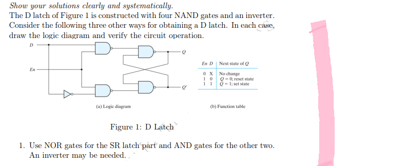
Transcribed Image Text:Show your solutions clearly and systematically.
The D latch of Figure 1 is constructed with four NAND gates and an inverter.
Consider the following three other ways for obtaining a D latch. In each case,
draw the logic diagram and verify the circuit operation.
D
En D
Next state of Q
En
0X
No change
10
11
Q = 0; reset state
Q-1; set state
(a) Logic diagram
(b) Function table.
Figure 1: D Latch
1. Use NOR gates for the SR latch part and AND gates for the other two.
An inverter may be needed.
Q
Expert Solution
This question has been solved!
Explore an expertly crafted, step-by-step solution for a thorough understanding of key concepts.

Step by step
Solved in 2 steps with 1 images

Knowledge Booster


Learn more about
Need a deep-dive on the concept behind this application? Look no further. Learn more about this topic, electrical-engineering and related others by exploring similar questions and additional content below.Recommended textbooks for you