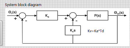
System block diagram O,(s) Ka Om(s) P(s) K₁s Kv=Ka*Td


Q: Help
A: Step 1:Step 2:Step 3:Step 4:
Q: Q1: Find Lea at the terminals of the circuit in Fig. 6.75. a 6 mH 8 mH 5 mil 12 mH 8 mH 6 mH 4 mH b…
A:
Q: Please answer in typing format
A: Step 1:pole = 6In block rotor test the wattmeter indicates only the copper loss…
Q: There is an example of this in my book, im not sure how they got the final answer can you pleaseee…
A: Step 1:
Q: Here A= 18,B=16 please answer in typing format
A:
Q: Please answer in typing format
A: Step 1:Step 2:Step 3:
Q: H.W: Picosecond laser is working with 100 kHz (Prr) and 10 ps pulse duration. The measured average…
A: Step 1:Please give helpful rating Step 2: Step 3: Step 4:
Q: Q.4: Find the Laplace Transform of the following. L{te-2t - Set 0 et sin 5t dt
A:
Q: Please answer in typing format
A: Step 1:Step 2:Step 3:Step 4:
Q: Help
A: Step 1: For maximum power transfer theorem the load resistance is equal to equivalent resistance of…
Q: each, 30 pts) 3- For the Boolean function F = wx'y + wy'z + wyz' + w'y'z + xy (a) Obtain the truth…
A: a) To obtain the truth table of the Boolean function F = wx'y + wy'z + wyz' + w'y'z + xy and…
Q: Please help with these parctice problems so I may study from them
A: based on your description of the image being a circuit with a voltage regulator, here are some…
Q: Asenkron which two losses were the iron losses in the engines in oluş Oa. Friction losses and…
A: Based on the image you sent, it appears to be a circuit diagram for a boost converter. Here's a…
Q: In this problem, we are interested in designing an FIR filter with input-outputrelationshipy[n] =…
A: a) To design the FIR filter with the given specifications, we can start by writing the filter's…
Q: The below circuit is excited with an AC source with the indicated amplitude and phase. Please…
A:
Q: 2.2 A vector p is 10 units long and is perpendicular to vectors q and r described here. Express the…
A: Step 1: Step 2: Step 3: Step 4:
Q: 3. The 6-V zener diode in Fig. 7-12 has a maximum rated power dissipated of 690 mW. Its reverse…
A: (3): If you have any queries, please comment.
Q: Determine the voltage between the open bridge terminals A and B in the figure
A: KIRCHHOFFS CURRENT LAW: It states that the algebraic sum of currents entering into the node is…
Q: please solve a to c detailed step by step solution thank you
A: Step 1:(a)Direct Form I structure:In the direct form I structure, the system function is implemented…
Q: a mulching plant uses a large motor to shred logs into small pieces. It takes the chipper motor 10…
A: Here's a breakdown of the mulching plant control system using start-stop pushbuttons, considering…
Q: Two long, parallel wires carry currents of I₁ = 3.18 A and 12 = 4.90 A in the direction indicated in…
A: Part (a) Recall that the dot represents the current flowing out of the page. By the right-hand…
Q: Given a range of values for vs and v0, how are these calculated for v0 and how is the range for vs…
A:
Q: Please answer in typing format
A: Step 1: The microwave spectrum band refers to a range of electromagnetic frequencies typically…
Q: 10.1 - A bipolar transistor is connected to a resistive load as shown in Figure 10.7. The source…
A: Step 1:Given:Vcc=40VoltsRL= 10 ohmsVCE= 0.1 VoltsBeta= 5 Load current IL= Ic:…
Q: Pls show neat and whole solution
A: Step 1:Step 2:Step 3:
Q: ли 6K +37 §6K I 6V 2K √2 mA (I₂ Find (1°) by mesh? 12:49 م
A: Step 1:Step 2:
Q: Name three (3) ways in which you can improve the energy efficiency in combustion systems
A: Three methods for increasing energy efficiency in combustion systems include: 1. Use of…
Q: Using source transformations, find v0 if it is 12.5 V.
A:
Q: 9. For practice question only need reference. Thanks for the help! show solution.
A:
Q: The diagram below shows a capacitive circuit supplied by two different sources. Position 1: E1=15v…
A: Step 1: Step 2: Step 3: Step 4:Step 5:Step 6:Step 7:
Q: show all the workk asap
A: Step 1:Step 2:
Q: A boost converter is modeled by including a switch resistance, sw = 0.08 an inductor resistance, r₁…
A: a) To derive the relation for ( Vo/Vin ) considering the non-ideal effects of the boost converter,…
Q: Calculate the convolution for the following tow functions f(t) & x(t)? x(t) (a) 2 1 2 2
A: First i write the function of f(t) and x(t) f(t)={2−t0for 0≤t≤2otherwise x(t)={10for…
Q: Can you check if my answers are correct (a) Determine the time constant of the circuit. T = 5.6ms…
A:
Q: 4. The transistor in the amplifier below has been biased such that IC - 0.3mA (no need to do DC…
A: Step 1:Step 2:Step 3:
Q: Please show the full steps. Thanks.
A: Step 1:
Q: i know you have to find the zero input response first, before zero state response so if you only…
A: zero input response MEANS THAT THERE IS NO INPUT so we will consider x(t) = 0now our equation for…
Q: From the image answer the following: 1. Calculate the (lagging) power factor of the total load of…
A:
Q: If v_1 = 5.00 V, v_2 = 1.79 V, and i_1 = -0.32 mA, how are these found using node-voltage analysis…
A:
Q: Mechanical Engineering: I need an expert solution provided in handwritten format with a clear and…
A:
Q: EXERCISE 13.7.2 (a) - 882 20s + 500 Find the initial and final values of the time function f(t) if F…
A: Step 1: Step 2: Step 3: Step 4:
Q: the label value of the 3-phase asynchronous motor is 380 V, 4A, 50 hz, power factor 0.8, 1.5kW, 950…
A:
Q: Plants Draw the single line and full schematic of the Vavien (multiway switch) installation
A: In a Vavien switch (also known as a multiway switch) installation, there are multiple switches that…
Q: Please show the full steps, thanks.
A:
Q: Answer the following questions regarding Makefile. . What chmod +x. In the code below for a…
A: In the provided Makefile excerpt:```makefile REM = rm LIB = libutil clean: $(REM) *. *.out $(LIB)…
Q: 4) 10% Derive and plot the amplitude spectrum of f (t) = sin 10t. Assume the fundamental frequency…
A: Step 1:
Q: 3 1 м w 255 510 YA 5 200 Find I° by using super position 3:17 ༥༤ 3:16 ص
A: Step 1:Step 2:Step 3:Step 4:
Q: Final The following figure, presents the frequency synthesizer of an FM receiver. The 'Programmable…
A: Step 1: Step 2: Step 3: Step 4:
Q: Please answer in typing format
A: Let's start with part (a): Given:Pavg=100mWVs=3VRs=20ΩRL=1kΩ We'll use the formula…
Q: Q65. For the fixed-bias JFET shown below if Ip-10mA, what is the value of the Vps? 15 V 7.5 V 00+…
A: Step 1: Since source S is connected to ground, VS=0V Step 2: Next using KVL:VDS=VDD−IDRDFor this…
what is the transfer function of this, P(s) = K / (s(tau*s+1))

Step by step
Solved in 2 steps with 2 images

- Considering the circuit. Determine Vz, IL, Iz, eI R270 if RL= 180Ω do the same but with RL = 470ΩThe givens are I1 = 0.219A, R1 = 66 ohms, R2 = 38 ohms, C = 0.1 farads. What is Vc across the capacitor at time t = 4.58 seconds?TII 7.) A show window 8.8 m in length is to be given this VA loading. A. 5860 B. 5866 C. 8800 D. 8866
- the root locus (draw asymptotes, find their angles, break away points etc ) for the follo aymmddetermmethevalucofkwhmhmakesthesystmnomllmry What is the fre (Nul:e. If you do not show your complete work, credits will not be assigned) k Gl - N L)If a phasor representation of a current is given by I = 70.7 ∠45° A, it is equivalent toFind: A+B+C Where, A=(246.8, 50°) B=(346.89,320°) C= (296.84,140°)
- Source voltage from Channel 1 output of oscilloscope and VR(t) and VL(t) voltages from Channel 2 output are desired to be observed by applying TTL signal to a series RL circuit with inductance value RL=270 mH, series R resistance 2.6 K and inductance internal resistance Rin=430 Ω. . The settings for the oscilloscope are as follows. Channel 1 Volt/div adjustment 2V Channel 2 Volt/div adjustment 2V Time/div=0.1ms Since the time t=5τ is 4.4 square units, a) If VL(t) voltage is desired to be observed from Channel 2, draw the required circuit diagram with oscilloscope channel connections. b) Plot the VR(t) and VL(t) waveforms to scale according to the 4V TTL source condition, showing the 5τ and τ times. Compare the τ value you obtained with the τ value you will theoretically calculate. c) If the unit square number of the peak value on the vertical axis at the end of t=5τ of the VR(t) voltage seen in Channel 2 is 1.4, find the current passing through the series RL circuit. d) Explain…Please i need full information about this topic please sir step by step I need for paresention (Huygen’s construction for a spherical) Please sir i need all information for my presentationCircuit analysis!!! please help. circle final answer
- Convert this hexadecimal system to dual system. 1. 3D 2. 7F Convert the dual system to hexadecimal: 3. 011101 4. 10101Given a Routh table below, is it stable or unstable? Explain why. (It's sign changes, poles etc.) s4 1 35 264 s3 1 5 0 s2 30 264 0 s1 -263 5/6 0 0 s0 -30.01 0 0Determine whether the given system is time-invariant. Show Proof. y[n] = -x[-n+1]+2