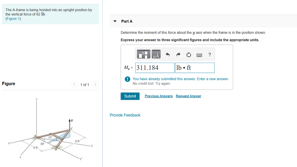
The A-frame is being hoisted into an upright position by the vertical force of 62 lb . (Figure 1)
Q: Sketch a free body diagram that can be used to determine a relation between the force that can turn…
A: FBD
Q: Q1: The shaft shown in Figure (1) is supported by two bearings and carries two V-belt sheaves.
A:
Q: The box is lifted using a pulley as shown in the figure. Find the maximum load that can be supported…
A:
Q: Draw the free body diagrams for each part in the figures below:
A: To draw the free body diagram.
Q: 4. The system of knotted cords shown in Fig P-317 support the indicated weights. Compute the tensile…
A: Given data Given force system in the string
Q: Draw a frame diagram to show their arrangement qualitatively, and solve for "T.
A: Solution
Q: Calculate the force the biceps muscle must exert to hold the forearm and its load as shown in the…
A:
Q: (13%) Problem 5: A shop sign weighing msg hangs from one end of a uniform beam weighing mpg. A hinge…
A:
Q: Make an illustration for this problem and label it completely. This lever has a fulcrum that they…
A:
Q: A column is loaded with a horizontal 100 N force. In which section are the internal loads the…
A: The load is given as 100 N. To find: The section in which the internal loads are minimum.
Q: Draw a free body diagram of part AD and part DCB. Show all detail. The compound is supported by a…
A:
Q: Figure 2 shows a countershaft carrying two V-belt pulleys. Pulley A receives power from a motor…
A:
Q: QI: A: Draw a Free-Body Diagram of the bars AD and BC shown in the figure. Assume all hinges to be…
A:
Q: Draw the free body diagrams for each part in the figures below; 3 it 2.
A: Note:As per our guidelines we are supposed to answer only one question. Kindly repost other…
Q: Make an illustration for this problem and label it completely. This lever has a fulcrum that they…
A:
Q: All problem solutions must include an FBD. F3-1. The crate has a weight of 550 lb. Determine the…
A:
Q: A. Draw the F.B.D. of the frame shown in Fig. (4-A).
A: To Draw the FBD of the given loading
Q: A bar is loaded and supported as shown in Fig. Draw an axial force diagram for the bar. 10 kN 10 kN…
A: Reaction at D can be determined as (Taking upward forces as +ve) Split the bar in parts and…
Q: The section of rope between Member-AD and Sheave-F is _____. options: 1 a two-force member 2 a…
A: Section of rope between member AD and Sheave F is a TWO FORCE MEMBER .
Q: Summary: Frames and Machines Figure 2 shows and assembly that is pinned at points A, B and D. (a) Is…
A: Collapsible A Collapsible structure is one that is not a rigid unit by itself but depends on its…
Q: find the forces in all joints
A: Consider the free body diagram of the pulley. From the moment equilibrium about the center of the…
Q: For the figure shown below, compute the normal force in section 1. Neglect the weights of the…
A:
Q: 1. Draw a FBD for the cylindrical tub before the metal object is added, clearly labeling all forces.…
A: When a body is immersed in water , the following forces acts on the body 1) Weight of the body 2)…
Q: Calculate the reaction forces at pin A. Calculate the magnitude and direction of reaction at the…
A:
Q: DIRECTIONS: Part 1: Set up a study about types of trusses and its importance and applications.…
A: Since you have posted a question with multiple sub-parts, we will solve PART 2 sub-parts for you. To…
Q: required force P,
A: To find Force P
Q: Q4/ Calculate the magnitude of the force supported by the pin B and roller support A for the bell…
A: Given: The magnitude of the force is F=220 N. The magnitude of the couple is M=50 N·m. Draw the…
Q: Figure Q3(a) If the angle of inclination of the string connecting pulley and the block is decreased,…
A: Let us draw the free body diagram Using the condition of the equilibrium T=Weight of the block
Q: Calculate the reaction A of the pin on bar AD of figure *
A:
Q: 8. Fig. 8 shows a simple aircraft landing gear, consisting of a spring and hydraulically loaded…
A:
Q: Make an illustration for this problem and label it completely. This lever has a fulcrum that they…
A:
Q: Problem 2: A hydraulic press has a ram of 20 cm diameter and a plunger of 3 cm diameter. It is used…
A:
Q: Q2: The tool shown in Fig.2 is used in a gluing operation to press a thin laminate to a thicker…
A:
Q: 13-12. Figure P13.12 shows a mechanism that is used to shear thin-gauge sheet metal. If a 200-N…
A: Given DataF=200NHere the free body diagram
Q: A 2 kN/m -5m- Figure 4 3 m 10 kN Į -2 m- B
A: Given
Q: Determine the support reactions on the member in figure. The collar at is fixed to the member and…
A: Given data: P = 900 N M = 500 N-m
Q: 4. How high can the worker safely climb the ladder? A ladder is leaning against a wall as shown in…
A:
Q: Draw a FBD (Free Body Diagram) showing all the forces (Not Components).
A: In this problem, it is assumed that the weight of the wrapped thin sheet is acted at the center of…
Q: Draw the Free-Body Diagram of member BCD. The pin at C is in a smooth slot.
A: To Draw Free Body Diagram of member BCD
Q: Sketch a pulley system that will give a 2 to 1 mechanical advantage. Provide a free body diagram…
A: Mechanical advantage is defined as the ratio of output force to the input force. Its value must be…
Q: 2. A roped is stretched between two rigid poles 40 feet apart. A load of 100 lbs was placed at the…
A: Here,tanθ=205⇒θ=tan-1(205)⇒θ=75.963οWriting equlibrium equation for…
Q: A link in a mechanism for an automated packag- ing machine is subjected to a direct tensile force of…
A: Given data as per question Force = 1720 lb Side of link = 0.40 in
Q: 3-5.19. A 12-ft bar of negligible weight rests in a ho on the smooth inclines in Fig. P-3-5.19 (p.…
A: Given data T=100lb P=200lb L=12ft
Q: draw the free-body diagrams for the entire assembly (or structure).
A: To draw the FBD of each structure Determine total no of unknowns Total no of independent equations…
Q: Where must a 0.80-kN object be hung on a uniform, horizontal, rigid 100-N pole so that a girl…
A:
Step by step
Solved in 2 steps
- The homogeneous bar AB weighs 25 lb. Determine the magnitudes of the forces acting on the bar at A and B. Neglect friction.Find the stable equilibrium position of the system described in Prob. 10.56 if m = 2.06 kg.PROBLEM 4: The boom OC is subjected to tension forces at A and C. It is known that the tension in A is 26 kN and at C is 12 kN. Unit vector CE. (ANSWER: -0.38i-0.87j+0.32k) Tension at A. (ANSWER: 13.20i-15.8j+15.8k kN VECTOR COMPONENT FORM) Moment about O due to the given forces. (ANSWER: 78.71i+0j+3.2k kN VECTOR COMPONENT FORM)
- Force P is applied as shown on the 13.5 mm thick plate. P = 100 kN. Holes are oversized causing all rivets to always proportionately react to load applied on the plate. 1. Which of the following most nearly gives the force in rivets if P is applied at the centroid of four(rivets)? a. 50 kN b. 30 kN c. 25 kN d. 40 kN 2. Which of the following most nearly gives the force in rivets if only moment equals P times e is applied at the centroid of four(rivets)? a. 12.567 kN b. 10.451 kN c. 32.672 kN d. 17.678 kN 3. Which of the following most nearly gives the maximum force in rivets due to combined effect of P and torque? a. 42.28 kN b. 40.93 kN c. 39.53 kN d. 37.34 kN 4. Considering shearing in bolts, what is the minimum required diameter if allowable shearing stress in bolts is Fv/2, Fv = 372 MPa a. 27.34 mm b. 14.53 mm c. 16.45 mm…Topic: Couples, Resultant of Force Systems & Equilibrium If F1 = 10N, F2 = 15N, F3 = 8N, F4 = 10N, F5 = 18N, and the length of te side of a red square is 1m. Calculate magnltude (+ for CCW, - for CW) of the resuItant moment (N-m) about point A. Calculate the magnitude of the reItant f0rce (N). (Answer: 50.80Nm, 20.33N)Determine the algebraic sum of the moments of forces relative to a point in F = 10.0 N; m =9.0 Nm, q =8.0 N/m
- Q4: of a car غطاء محرك The i Jul. The bonnet is held open at an angle of 60° to the horizontal by a vertical force V applied at one end of the bonnet (shown on the diagram). The long, has a weight of 25 N and its center diagram shows the open bonnet bonnet is 0.90 m of gravity G is 0.35 m from the hinge at O. 1) On the diagram, draw and label the two forces other than V acting on the bonnet. By taking moments about A, Proof that the vertical 2) force V applied at the end of the bonnet is 9.7 N. 3) Calculate the magnitude of the force acting at the hinge ON.SITUATION 7: Three forces P1, P2, and P3 are acting on a semi-circular structure as shown in Fig. THA-33. Support at A is hinge and support at B is roller. Given: a = 1 m; P1 = 1.8 kN; P2 = 0.9 kN; P3 = 0.45 kN; θ = 30⁰; β = 45⁰. Calculate the resultant of the three forces (in kN). (Answer: 2.45) Calculate the vertical reaction at B (kN). (Answer: 1.06) Calculate the reaction at A. (Answer: 1.63)The weight of the base is negligible What is the moment of the weight of Part G3 about Point A? What is the moment of the weight of Part G3 about Point B? Are the two moments equal? Explain
- Passing an exploratory section through the body and exposing the internal forces acting on the exploratory section. Mxy represents torsional moment about y-axis. True of FalsePassing an exploratory section through the body and exposing the internal forces acting on the exploratory section, Mxy represents Torsional Moment about x-axis.The three-bar truss in Fig. a is subjected to a horizontal force of 5 kip. If the cross-sectional area of each member is 0.20 in2, determine the horizontal displacement at point B. E = 29(103) ksi.