The beam shown below is acted upon by a triangular distributed load, a couple moment, and a point force as shown. It is supported by a roller at A and a pin at B. M 3 m 1m 1m The applied forces/moments are: w= 150 N/m M = 65 N-m F = 20 N I. Determine the reaction forces at A and B. ii. Find the location of zero shear between A and B. i. Determine the absolute maximum bending moment for the beam. iv. Draw the shear force diagram for the beam. v. Draw the bending moment diagram for the beam.
The beam shown below is acted upon by a triangular distributed load, a couple moment, and a point force as shown. It is supported by a roller at A and a pin at B. M 3 m 1m 1m The applied forces/moments are: w= 150 N/m M = 65 N-m F = 20 N I. Determine the reaction forces at A and B. ii. Find the location of zero shear between A and B. i. Determine the absolute maximum bending moment for the beam. iv. Draw the shear force diagram for the beam. v. Draw the bending moment diagram for the beam.

Mechanics of Materials (MindTap Course List)
9th Edition
ISBN:9781337093347
Author:Barry J. Goodno, James M. Gere
Publisher:Barry J. Goodno, James M. Gere
Chapter4: Shear Forces And Bending Moments
Section: Chapter Questions
Problem 4.3.6P: The beam ABC shown in the figure is simply supported at A and B and has an overhang from B to C. The...

Related questions
Question
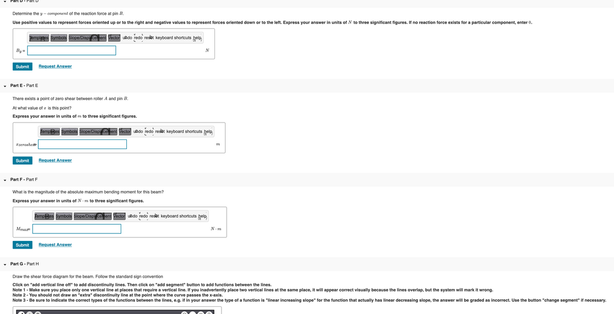
Transcribed Image Text:Determine the y – component of the reaction force at pin B.
Use positive values to represent forces oriented up or to the right and negative values to represent forces oriented down or to the left. Express your answer in units of N to three significant figures. If no reaction force exists for a particular component, enter 0.
Jemplates Symbols Slope/Displacement Vector uado redo reset keyboard shortcuts help,
By=
N
Submit
Request Answer
Part E - Part E
There exists a point of zero shear between roller A and pin B.
At what value of x is this point?
Express your answer in units of m to three significant figures.
Templates Symbols Slope/Displacement Vector uado redo reset keyboard shortcuts help
xzerosher
m
Submit
Request Answer
Part F- Part F
What is the magnitude of the absolute maximum bending moment for this beam?
Express your answer in units of N . m to three significant figures.
Templates Symbols Slope/Displacement Vector uado redo resat keyboard shortcuts help
MmaF
N. m
Submit
Request Answer
Part G - Part H
Draw the shear force diagram for the beam. Follow the standard sign convention
Click on "add vertical line off" to add discontinuity lines. Then click on "add segment" button to add functions between the lines.
Note 1- Make sure you place only one vertical line at places that require a vertical line. If you inadvertently place two vertical lines at the same place, it will appear correct visually because the lines overlap, but the system will mark it wrong.
Note 2 - You should not draw an "extra" discontinuity line at the point where the curve passes the x-axis.
Note 3 - Be sure to indicate the correct types of the functions between the lines, e.g. if in your answer the type of a function is "linear increasing slope" for the function that actually has linear decreasing slope, the answer will be graded as incorrect. Use the button "change segment" if necessary.
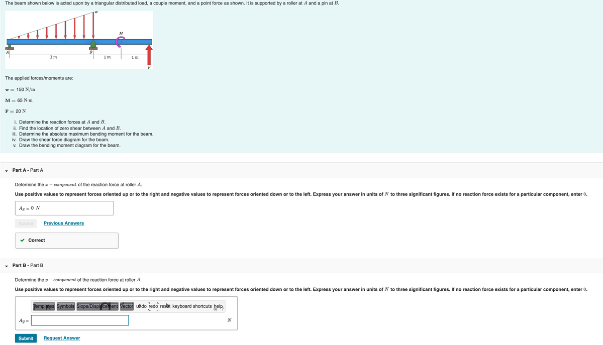
Transcribed Image Text:The beam shown below is acted upon by a triangular distributed load, a couple moment, and a point force as shown. It is supported by a roller at A and a pin at B.
3 m
1 m
1 т
F
The applied forces/moments are:
w = 150 N/m
M = 65 N•m
F = 20 N
i. Determine the reaction forces at A and B.
ii. Find the location of zero shear between A and B.
iii. Determine the absolute maximum bending moment for the beam.
iv. Draw the shear force diagram for the beam.
v. Draw the bending moment diagram for the beam.
Part A - Part A
Determine the x – component of the reaction force at roller A.
Use positive values to represent forces oriented up or to the right and negative values to represent forces oriented down or to the left. Express your answer in units of N to three significant figures. If no reaction force exists for a particular component, enter 0.
Ag = 0 N
Submit
Previous Answers
Correct
Part B - Part B
Determine the y – component of the reaction force at roller A.
Use positive values to represent forces oriented up or to the right and negative values to represent forces oriented down or to the left. Express your answer in units of N to three significant figures. If no reaction force exists for a particular component, enter 0.
Templates Symbols Slope/Displacement Vector uado redo reset keyboard shortcuts help,
Ay =
N
Submit
Request Answer
Expert Solution
This question has been solved!
Explore an expertly crafted, step-by-step solution for a thorough understanding of key concepts.

This is a popular solution!

Trending now
This is a popular solution!

Step by step
Solved in 4 steps with 4 images

Knowledge Booster


Learn more about
Need a deep-dive on the concept behind this application? Look no further. Learn more about this topic, mechanical-engineering and related others by exploring similar questions and additional content below.Recommended textbooks for you
Mechanics of Materials (MindTap Course List)
Mechanical Engineering
ISBN:
9781337093347
Author:
Barry J. Goodno, James M. Gere
Publisher:
Cengage Learning
Mechanics of Materials (MindTap Course List)
Mechanical Engineering
ISBN:
9781337093347
Author:
Barry J. Goodno, James M. Gere
Publisher:
Cengage Learning