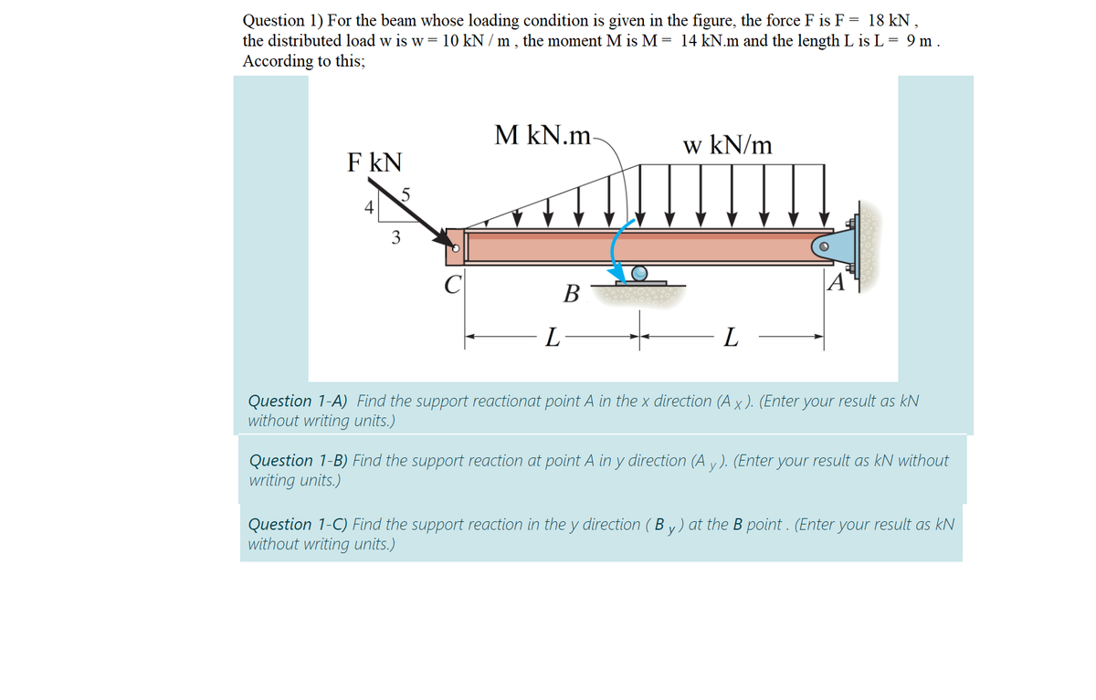
Question 1) For the beam whose loading condition is given in the figure, the force F is F = 18 kN, the distributed load w is w = 10 kN / m , the moment M is M = 14 kN.m and the length L is L = 9 m . According to this;
Q: A beam with length L is fixed at both ends. It is loaded with a concentrated force P at L/3 from the…
A:
Q: Draw the shear-force and bending-moment diagrams for a simple beam as shown in Figure Q2 with a…
A:
Q: Homework; In Figure below, a cantilever beam is subjected to an inclined force (P); calculate: 1-…
A:
Q: Q3: Draw the shear force and bending moment diagrams for the loaded beam shown (see figure below). (…
A: Draw the free-body diagram of the beam.
Q: The constructed shear force diagram (SFD) for the simply supported beam with a Triangle distributed…
A: To find: (a) The reaction at the supports. (b) The shear force at supports. (c) The value of x. Free…
Q: The inverted T-beam supports three concentrated loads as shown in the fig?ure. Find the maximum…
A: Given that: The bending stresses are not to exceed 3.5 ksi in tension and 8 ksi in compression 1. It…
Q: La7 For the simply supported beam and the loading shown in the figure find the * Chinge forces (B)…
A: It is required to determine support reaction force
Q: Q2: A simply supported beam has a span of 4m and carries a uniformly distributed load of 60 kN/m…
A: Given data: The uniformly distributed load is w = 60 kN/m and span of L = 4 m. The concentrated…
Q: For the beam shown in the figure below: (i) (ii) (iii) Determine all the support reactions. Draw the…
A: Given:- Beam with different loading and supports. C and E are hinges B, F, and G are roller A is pin…
Q: The distributed load on the T-section beam in the figure is w = 100 kN/m. The tensile stress that…
A: Bending stress in beams When external load acts on beam shear force and bending moment are set up at…
Q: Figure Q2 shows the free body diagram of a 10 m long beam AD of uniform cross-section, simply…
A:
Q: Situation 12: The simply supported beam in FIGURE SOM-008 is fabricated by gluing together three 160…
A: For the given simply supported beam maximum bending stress in the planks = 24 MPa To determine…
Q: Consider a beam with boundary conditions, loading, and cross-section given below. In addition to the…
A: GIVEN: *P=5 kips=5 Kips = 22.2411 kN *M=144 k-in=16.2698 kNm TO FIND: (a) The normal (flexural)…
Q: A flanged wooden shape is used to support the loads shown on the beam. The dimensions of the shape…
A:
Q: Consider the beam shown in the figure. Suppose that the distributed load w = 650 lb/ft . Follow the…
A: Solution ; As the loading is symmetric, so reaction at the support will be equal :…
Q: Draw the complete shearing force and bending moment diagram for the beam shown in figure. Show…
A:
Q: For the simply supported beam subjected to the loads shown. Let a=3.00 m, b=4.00 m, PB = 30kN, and…
A: Given data: ◆ The values of point loads applied on the beam: PB = 30 kN , Pc = 65 kN ◆ The length of…
Q: Anchor point of the beam given in the figure is fixed support and B point is movable support. Find…
A:
Q: beam ABCDE is 5 m in length and loaded as shown in Figure Q3. Draw the S.F. and B.M. diagrams for…
A:
Q: 7) Consider the beam in the figure below. Take w=50 kN/m. The 40 kN force makes an angle of 60…
A:
Q: Problem 3. Problem. The upper beam in figure is supported by a reaction R3 at D and a roller at C…
A:
Q: 3-In the figure given below, P(load) and M(moment) effects from the mid point of the fixed beam from…
A: Both ends of a fixed or built-in beam are firmly fastened, ensuring that the slope at the ends…
Q: The overhanging beam ABC in figure carries a concentrated load and a uniformly distributed load.…
A:
Q: he upper beam in the figure is supported by a reaction R3 and a roller at A which separates the…
A:
Q: 2: For the beam shown in Fig.(2), find the reaction forces at supports A and B respectively? %) 20…
A:
Q: Specily where th (c) Find the support reactions at A and C (As shown in the figure, A is a pin…
A:
Q: For the simply supported beam subjected to the loads shown. Let a=3.00 m, b=4.00 m, PB = 30kN, and…
A:
Q: Figure Q2 shows the cross section of a beam. The beam is simply supported over a span of 6 m and…
A:
Q: An electrical worker stands in the bucket that hangs from a pin at end D of the boom of the cherry…
A: The weight of worker and bucket together is 300lb Therefore the Free body diagram is
Q: In the beam loading system given below, A is a simple and C is a sliding support. The outer diameter…
A:
Q: cross-section, simply supported at locations A and C. A uniformly distributed load of 10 kN/m is…
A: Since you have asjed a multi-question, thus according to our guidelines we can provide you the…
Q: 1. For the simply supported beam shown in Fig. 1, calculate the support reactions, write the shear…
A: Given: The beam is shown below: Assume the value of s as 1.
Q: Q3: Draw the shear force and bending moment diagrams for the loaded beam (shown (see figure below).…
A:
Q: For the fixed-ended beam shown in figure below, each end moment equals: P A В L/2- L/2- P/2 O P/8…
A: For the fixed-ended beam shown in figure below, each end moment equals: P/2 P/8 P/16 P/4
Q: A flanged wooden shape is used to support the loads shown on the beam. The dimensions of the shape…
A:
Q: Draw diagram shear force and bending moment to cantilever beam which shown in the figure. W=5 KN/m…
A: The Shear Force Diagram (SFD) and Bending Moment Diagram (BMD) are very important tools to analyze a…
Q: Problem 4: A barge shown in the figure carries 290kN/m and 580KN/m loads. 3m 6m Зт 580 kN/m a. Find…
A: The given beam is as shown below, Let the upward load acting on the beam is w, (a) Balancing…
Q: Problem 4.6 Consider the uniform, horizontal cantilever beam shown in Fig. 4.54. The beam is fixed…
A:
Q: Problem 1. The simply supported beam in the figure is loaded by the counterclockwise Co at B. Draw…
A: If a beam is supported at both the endpoints (extreme ends of the beam) , the beam is termed as the…
Q: Figure 3 below shows a 16 m length of beam with a pinned support at A and roller support at C. The…
A: 1) Free body diagram of the beam and calculation of reaction forces The free body diagram of the…
Q: For structural member steel beam with an overhang as shown below, determine a) the support…
A:
Q: A Portable Crane will be designed as shown in Figure which is able to withstand dynamic loads. Th…
A:
Q: An electrical worker stands in the bucket that hangs from a pin at end D of the boom of the cherry…
A: To find internal forces at section E
Q: Example 5: Draw the shear force and bending moment diagrams for the simply supported beam as shown…
A:
Q: The beam AB shown in the figure supportsa uniform load of intensity 3000 N/m acting over halfthe…
A: At first drawing the beam AB as shown in the figure Here 3000Nm is the uniform load of intensity
Q: Example The beam ABC is loaded via a 500 N.m couple and a 600 N force as shown. The beam is…
A:
Q: Question 4: For the beam shown in figure below, The weight W =2 kN. (A is pinned support and B is…
A: Draw the free body diagram of the beam: \
Q: Draw the Shear Force and Bending Moment diagrams stating the important values
A:
Q: Two beams (see figure) are loaded the same and have the same support conditions. However, the…
A: Solution: Given Data: Note: As you have answered multiple sub-parts, we can answer only three…
Step by step
Solved in 2 steps with 1 images
- A C 200 x 17.1 channel section has an angle with equal legs attached as shown; the angle serves as a lintel beam. The combined steel section is subjected to a bending moment M having its vector directed along the z axis, as shown in the figure. The cent roi d C of the combined section is located at distances xtand ycfrom the centroid (C1) of the channel alone. Principal axes yl and yvare also shown in the figure and properties Ix1,Iy1and 0pare given. Find the orientation of the neutral axis and calculate the maximum tensile stress exand maximum compressive stress if the angle is an L 76 x 76 x 6.4 section and M = 3.5 kN - m. Use the following properties for principal axes for the combined section:/^, = 18.49 X 10⁶ nrai4,/;| = 1.602 X 106 mm4, ep= 7.448*(CW),_r£ = 10.70 mm,andvf= 24.07 mm.Find expressions for shear force V and moment M at x = x0of beam AB in terms of peak load intensity q0and beam length variable L. Let x0= L/2.A beam supporting a uniform load of intensity q throughout its length rests on pistons at points A, C and B (sec figure). The cylinders are filled with oil and are connected by a tube so that the oil pressure on each piston is the same. The pistons at A and B have diameter d1and the piston at C has diameter D2. (a) Determine the ratio of d2to d1so that the largest bending moment in the beam is as small as possible. Under these optimum conditions, what is the largest bending moment Mmaxin the beam? What is the difference in elevation between point C and the end supports?
- .10 A built-up bourn supporting a condominium balcony is made up of a structural T (one half of a W 200 x 31.3) for the top flange and web and two angles (2 L 2 / b / 6.4. long legal back-lo-backl lot the bottom flange and web. as shown. The beam is subjected to a bending moment .1/ having its vector at an angle ft lo the z axis (see figure). Determine the or ion ta I ion of the neutral axis and calculate the maximum tensile stress ir, and maximum compressive stress tr. in ".he beam. .Assume that 9 = 30°andM = 15 kN · m. Use the numerical properties: c =4.111mm, c2 =4.169 mm, of = 134 mm, I, = 76 mm, A = 4144 mm 3 =3.88 X 106 mm 4, and = 34.18 X 10 mm 4.A beam made up all woun equal leg angles is subjected to a bending moment M having its vector .u an angle (i) lo lire axis (see figure paria). (a) For the position shown in lire figure, determine lire orienlalion of lire neulral axis and calculate lire maximum tensile s'av-s ir, and maximum compressive stress (b) The two angles are now inverted and attached back-lo-back lo lorn, a lintel beam that supports two courses of brick facade i see figure part b). Find the new orientation of the neutral axis and calculate the maximum tensile slress r. a::d maximum compressive s'avsrr . in I he beam using 6 = 30° and M = 30 kip-in.The beam ABC shown in the figure is simply supported at A and B and has an overhang from B to C. The loads consist of a horizontal force P1= 4,0 kN acting at the end of a vertical arm and a vertical force P2= 8.0 kN acting at the end of the overhang, Determine the shear force Fand bending moment M at a cross section located 3,0 m from the left-hand support. Note: Disregard the widths of the beam and vertical arm and use centerline dimensions when making calculations, Find the value of load A that results in V = 0 at a cross section located 2.0 m from the left-hand support. If P2= 8.0 kN, find the value of load P1that results in M = 0 at a cross section located 2,0 m from the left-hand support.
- The cross section of a bimetallic strip is shown in the figure. Assuming that the moduli of elasticity for metals A and B are EA=168 GPa and EB= 90 GPa, respectively, determine the smaller of the two section moduli for the beam. (Recall that section modulus is equal to bending moment divided by maximum bending stress.) In which material does the maximum stress occur?The cross section of a composite beam made of aluminum and steel is shown in the figure. The moduli of elasticity are TA= 75 GPa and Es= 200 GPa. Under the action of a bending moment that produces a maximum stress of 50 M Pa in the aluminum, what is the maximum stress xs in the steel? If the height of the beam remains at 120 mm and allowable stresses in steel and aluminum are defined as 94 M Pa and 40 M Pa, respectively, what heights h and h. arc required for aluminum and steel, respectively, so that both steel and aluminum reach their allowable stress values under the maximum moment?Find expressions for shear force V and moment M at x = L/2 of beam BC. Express V and M in term s of peak load intensity q0and be a m length variable L.
- Find shear (V) and moment (M) at x = 3L/4 for the beam shown in Fig. a. Let MA= 24 kN m,P = 48 kN, L = 6 m, and q0= 8 kN/m. Repeat for the beam in Fig, b (first solve for the reaction moment at fixed support A).A cantilever beam AB having rectangular cross sections with varying width bxand varying height hxis subjected to a uniform load of intensity q (sec figure). If the width varies linearly with x according to the equation hx= bBxiL^ how should the height hxvary as a function of v in order to have a fully stressed beam? (Express hxin terms of the height hBat the fixed end of the beam.)Find expressions for shear force V and moment Mat x = 2L/3 of beam (a) in terms of peak load intensity q0and beam length variable L. Repeat for beam (b) but at x = L/2.