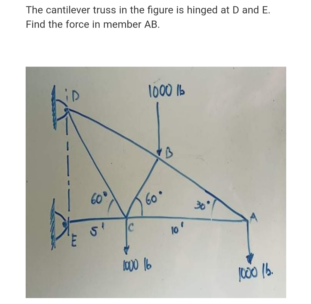
The cantilever truss in the figure is hinged at D and E. Find the force in member AB.


Q: The cantilever truss shown in the figure carries a vertical load of 30 kN . The truss is supported…
A: Given data as per question The load applied at the end of the truss =30 KN Distance between points A…
Q: The ship ladder in the figure is 1500 N and its center of gravity is at G. What must be the rope…
A:
Q: A post with a horizontal and inclined member supports a box whose weight is P, as shown in the…
A: Let FAC is the force in member AC and FAB is the force exerted by member AB. Consider tensile forces…
Q: The vertical force P of magnitude 100 kN is applied to the frame shown in the figure. Resolve P into…
A: P = 100 kN
Q: Consider the truss shown in the figure below. Calculate the force on the member BC. A 5 ft D
A: Given: The structure,
Q: The structure is supported by guy wires as shown in the figure. Neglect the weight of the members…
A: wires ac and BC are symmetrically attached and will therefore bear the same tensions. We will…
Q: For the plane truss shown in the figure below, determine the following: a. Force in member BF. b.…
A:
Q: 80 KN 50 KN 6.0 m 6.0 m 6.0 m 6.0 m 40 KN 100 KN
A:
Q: 4. For the frame shown in the figure, determine the horizontal and vertical components of the hinge…
A:
Q: In the figure below, the boom AC is supported in a ball and socket joint at C and by the cables AD…
A:
Q: Calculate the reactions at supports A and B of the truss in the figure. Neglect the weight of the…
A:
Q: In the frame in the figure, AC are horizontal elements and BE are vertical elements. Calculate the…
A: Given-
Q: Q4) A 500 lb buoy, with a 2 ft radius is tied to the bed of a lake using a steel cable. What is the…
A: Given, m = 500 lb r = 2 ft ρw = 62.4 lb/ft3
Q: For the structure shown in Figure, Compute the forces in all pines.
A:
Q: A boom with an angle of theta, supports a 1000 lbs load as shown in the figure. Assume that the…
A: Givenweight W=1000lbsforce exerted by boom =3 times tension in rope
Q: The force in the truss AB
A: Given data; Trusses support load of =100 NLength of each truss is=1.0Cross-sectional area=200…
Q: Compute the absolute internal force for the member of CD. Consider P = 251 kN.
A:
Q: Q/Draw free body diagram then find reactions at pin support (O) and smooth surface (B) take beam OB…
A:
Q: the roof truss in Fig. 3, is supported by a roller at A and B. Find the value of the reactions.
A: Solution:
Q: Isosceles triangular gate AB, as shown in the figure, is hinged at A. The horizontal force (P) is…
A: Given Data: The vertical distance between point A and free surface is, C=4 m. The vertical distance…
Q: The structure shown in Fig 4-4.17 consists of two simple trusses joined by bars Be, CF and DG. Find…
A:
Q: The slender plank shown in figure is held in equilibrium by the action of the force Fp. Find the…
A: Given, m = 200 kg
Q: The boom AB supports a load of W = 720 lb. The boom is supported by a ball-and-socket joint at A and…
A:
Q: For the frame shown in the figure , the axial force in member CD equals
A: F.B.D.
Q: In the truss system in the figure, the reaction forces on the supports and the forces acting on each…
A: A pin support will exert both horizontal and vertical components of reaction. The support A is pin…
Q: The 6-m pole ABC is acted upon by a 460-N force, P, as shown in the figure. The pole is held by a…
A:
Q: Q The two-steel shaft shown in figure have the same diameter and weight 170 lb cach. Neglect the…
A:
Q: Q2) A boom 20m long supports a load of 1200 kg as shown in the below figure. The cable BC is…
A: The given load and cable and the FBD is as shown below, T1=mgT1=12009.81T1=11.772 kN
Q: The roof truss shown in Fig. 3-17a is supported on rollers at A and hinged at B. The wind loads are…
A:
Q: For the rigid body below, Draw the Free Body Diagram and find the Reaction Force of pin support at…
A: Consider the free body diagram shown below for the truss.
Q: Find internal forces in membeis of te truss Shown 20K
A:
Q: 3: In Fig. 2, Find the Force in members DC, EC, EF Using Method of Sections and in Members AE & BG…
A: Given data as per the question Force applied at F =6 KN Force applied at G =2KN RA+RB=3+6+2=11…
Q: The boom of the wall crane 4m long is held at right angles to the wall by a wire that is attached to…
A:
Q: The roof truss shown in Fig. 3–17a is supported on rollers at A and hinged at B. The wind loads are…
A:
Q: Q/Draw free body diagram then find reactions at pin support (O) and smooth surface (B) take beam OB…
A:
Q: The roof truss shown in the figure has fixed support at F and roller support at A. Find the reaction…
A:
Q: A truck of mass 2 tonnes runs into a buffer stop having three buffer springs each of 10 kN/cm…
A:
Q: Q3: For the structure shown in Figure, Compute the forces in all pines. 50 Ib 80 Ib 6 ft (20 Degree)
A:
Q: A post with a horizontal and inclined member supports a box whose weight is P, as shown in the…
A: The given weight of the box is P. Consider the free body diagram as shown below for the joint C.…
Q: Determine all forces acting on member DEF of the frame shown in Figure below:-
A: To determine the force in the member DEF
Q: A beam has a pin support at A and a roller support at B. Given the load forces, find the support…
A: Given, The total length of the beam is 9 m.
Q: A 200-lb weight is suspended from a wall by means of a bracket, where the triangle BOD is in a…
A:
Q: A uniform bar 6 m long is held by ropes at the ends making angle 60° and 30°, respectively, with…
A:
Q: the space truss shown in Figure 4, member BC, CD and DB form an equilateral triangle in th…
A:
Q: As per the crane shown in the Figure. Determine the force member at CE.
A:
Q: 3. For the truss shown below, find the internal force of all members using method of sections. 120…
A: In three force members joint with no external load, when the two members are collinear, the third…
Q: e The two-steel shaft shown in figure have the same diameter and weight 180 lb each. Neglect the…
A: Given data: Weight of each block, W = 180 lb. Draw a free-body diagram of the upper shaft. Apply…
Q: Q The two-steel shaft shown in figure have the same diameter and weight 150 lb cach. Neglect the…
A:
Q: For the pinned frame in the figure, calculate the pin forces acting at point B, on member BD…
A:
Q: Consider the truss shown in the figure below. Calculate the force on the member BC.
A: Answer: The force in the member BC is 60 lbs (compression).


Trending now
This is a popular solution!

Step by step
Solved in 2 steps with 2 images


- A truss ABC supports a load W at joint B, as shown in the figure. The length L, of member Aß is fixed, but the length of strut BC varies as the angle is changed. Strut BC has a solid circular cross section. Joint B is restrained against displacement perpendicular to the plane of the truss. Assuming that collapse occurs by Etiler buckling of the strut determine the angle for minimum weight of the strut.A large precast concrete panel for a warehouse is raised using two sets of cables at two lift lines, as shown in the figure part a. Cable 1 has a length L1 = 22 Ft, cable 2 has a length L2= 10 ft, and the distance along the panel between lift points Band D is d = 14 ft (see figure part b). The total weight of the panel is W = 85 kips. Assuming the cable lift Forces F at each lift line are about equal, use the simplified model of one half of the panel in figure part b to perform your analysis for the lift position shown. Find the required cross-sectional area AC of the cable if its breaking stress is 91 ksi and a factor of safety of 4 with respect to failure is desired.The roof over a concourse at an airport is supported by the use of pretensioned cables. At a typical joint in the roof structure, a strut AB is compressed by the action of tensile forces Fin a cable that makes an angle = 75° with the strut (see figure and photo). The strut is a circular tube of steel (E = 30,000 ksi) with outer diameter d2= 2.5 in. and inner diameter d1= 2.0 in. The strut is 5.75 ft long and is assumed to be pin-connected at both ends. Using a factor of safety n = 2.5 with respect to the critical load, determine the allowable force F in the cable.
- A steel post (E=30×106) having thickness t = 1/8 in. and height L = 72 in. support a stop sign (see figure), where s = 12.5 in. The height of the post L is measured from the base to the centroid of the sign. The stop sign is subjected to wind pressure p = 20 lb/ft2 normal to its surface. Assume that the post is fixed at its base. What is the resultant load on the sign? (Sec Appendix E, Case 25, for properties of an octagon, n =8.) What is the maximum bending stress in the post? Repeat part (b) if the circular cut-outs arc eliminated over the height of the post.A sign of weight W is supported at its base by four bolls anchored in a concrete footing. Wind pressure P acts normal to the surface of the sign; the resultant of the uniform wind pressure is force fat the center of pressure (C.P). The wind force is assumed to create equal shear forces F/4 in the y direction at each boll (see figure parts a and c). The overturning effect of the wind force also causes an uplift force R at bolts A and C and a downward force (— R) al bolts B and D (see figure part b). The resulting effects of the wind and the associated ultimate stresses for each stress condition are normal stress in each boll (h — 60 ksi); shear through the base plate (th = 17 ksi); horizontal shear and bearing on each bolt ( tfur = 25 ksi and cr^ = 75 ksi): and bearing on the bottom washer at B (or D) (abor = 50 ksi).A soccer goal is subjected to gravity loads (in the - z direction, w = 73 N/m for DG, BG, and BC; w = 29 N/m for all other members; see figure) and a force F = 200 N applied eccentrically at the mid-height of member DG. Find reactions at sup ports C, D, and H.
- Find support reactions at 4 and Band then use the method of joints to find all member forces. Let b = 3 m and P = 80 kN.A cylindrical brick chimney of height H weighs w = 825 lb/ft of height (see figure). The inner and outer diameters are d1= 3 ft and d2= 4 ft, respectively. The wind pressure against the side of the chimney is p = 10 lb/ft2 of projected area. Determine the maximum height H if there is to be no tension in the brickwork.The truss ABC shown in the figure supports a vertical load W at joint B. Each member is a slender circular steel pipe (E = 30,000 ksi) with an outside diameter of 4 in. and wall thickness 0.25 in. The distance between supports is 23 ft. Joint B is restrained against displacement perpendicular to the plane of the truss. Determine the critical value Wcr of the load.
- Continuous cable A DB runs over a small friction less pulley al D to support beam OABC, which is part of an entrance canopy for a building (see figure}. The canopy segment has a weight W = 1700 lb that acts as a concentrated load in the middle of segment AB. (a) What is the maximum permissible value of load P at C if the allowable force in the cable is 4200 lb? (b) If P = 2300 lb, what is the required diameter of pins A, B, and D? Assume that the pins are in double shear and the allowable shear stress in the pins is 10 ksi.A crane boom of mass 450 leg with its center of mass at C is stabilized by two cables AQ and BQ (Ae= 304 mm2 for each cable) as shown in the figure. A load P = 20 KN is supported at point D. The crane boom lies in the y-z plane. (a) Find the tension forces in each cable: TAQand TBQ(kN}. Neglect the mass of the cables, but include the mass of the boom in addition to load P. (b) Find the average stress (s) in each cable.An L-shaped reinforced concrete slab 12 Ft X 12 ft, with a 6 Ft X 6 ft cut-out and thickness t = 9.0 in, is lifted by three cables attached at O, B, and D, as shown in the figure. The cables are are combined at point Q, which is 7.0 Ft above the top of the slab and directly above the center of mass at C. Each cable has an effective cross-sectional area of Ae= 0.12 in2. (a) Find the tensile force Tr(i = 1, 2, 3) in each cable due to the weight W of the concrete slab (ignore weight of cables). (b) Find the average stress ov in each cable. (See Table I-1 in Appendix I for the weight density of reinforced concrete.) (c) Add cable AQ so that OQA is one continuous cable, with each segment having Force T, which is connected to cables BQ and DQ at point Q. Repeat parts (a) and (b). Hini: There are now three Forced equilibrium equations and one constrain equation, T1= T4.