The capacitor in the below circuit was discharged prior to assembly and the circuit was in steady state before the switches were moved as indicated. Please calculate the indicated parameters at the given times. V₂ = 2 V, L = 10 nH. † = 0 6 пн L Vx Vy † = 0 100 nF 4 ΚΩ ΣΙΚΩ 1 k Vs Vx V₁ 4 nH ↓ |t0|t=0+ t = ∞ot = 1μst = 5μs Unit V V
The capacitor in the below circuit was discharged prior to assembly and the circuit was in steady state before the switches were moved as indicated. Please calculate the indicated parameters at the given times. V₂ = 2 V, L = 10 nH. † = 0 6 пн L Vx Vy † = 0 100 nF 4 ΚΩ ΣΙΚΩ 1 k Vs Vx V₁ 4 nH ↓ |t0|t=0+ t = ∞ot = 1μst = 5μs Unit V V

Delmar's Standard Textbook Of Electricity
7th Edition
ISBN:9781337900348
Author:Stephen L. Herman
Publisher:Stephen L. Herman
Chapter23: Resistive-inductive-capacitive Series Circuits
Section: Chapter Questions
Problem 3PP: The circuit is connected to a 60-Hz line. The apparent power in the circuit is 29.985 VA, and the...

Related questions
Question
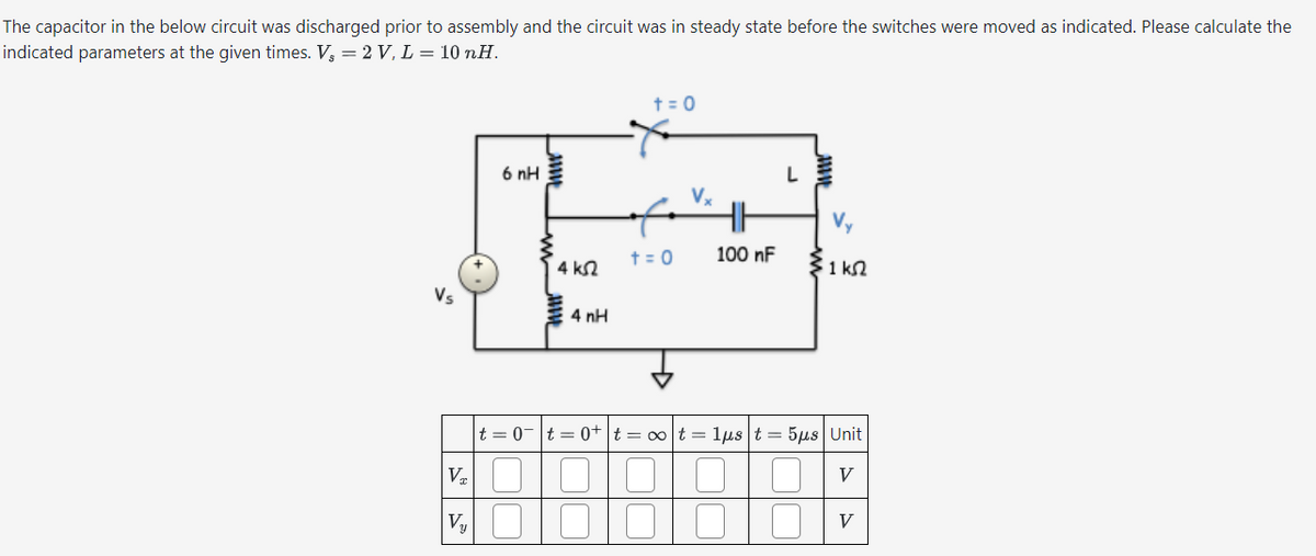
Transcribed Image Text:The capacitor in the below circuit was discharged prior to assembly and the circuit was in steady state before the switches were moved as indicated. Please calculate the
indicated parameters at the given times. V₂ = 2 V, L = 10 nH.
† = 0
6 пн
L
Vx
Vy
† = 0
100 nF
4 ΚΩ
ΣΙΚΩ
1 k
Vs
Vx
V₁
4 nH
↓
|t0|t=0+ t = ∞ot = 1μst = 5μs Unit
V
V
Expert Solution
This question has been solved!
Explore an expertly crafted, step-by-step solution for a thorough understanding of key concepts.

Step by step
Solved in 2 steps

Recommended textbooks for you
Delmar's Standard Textbook Of Electricity
Electrical Engineering
ISBN:
9781337900348
Author:
Stephen L. Herman
Publisher:
Cengage Learning
Delmar's Standard Textbook Of Electricity
Electrical Engineering
ISBN:
9781337900348
Author:
Stephen L. Herman
Publisher:
Cengage Learning