The closed-loop system transfer function of a control system is

Understanding Motor Controls
4th Edition
ISBN:9781337798686
Author:Stephen L. Herman
Publisher:Stephen L. Herman
Chapter54: The Operational Amplifier
Section: Chapter Questions
Problem 7RQ: Name two effects of negative feedback.

Related questions

Question
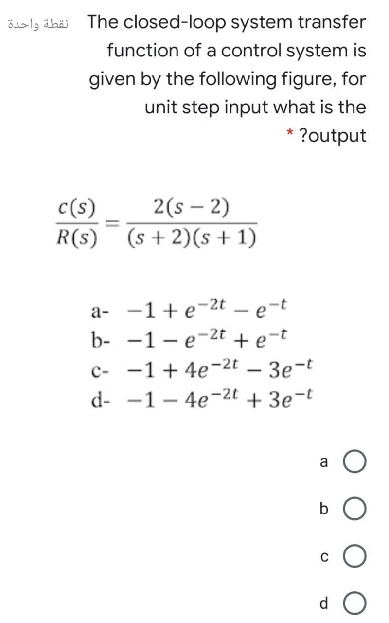
Transcribed Image Text:öalg äbäi The closed-loop system transfer
function of a control system is
given by the following figure, for
unit step input what is the
* ?output
2(s – 2)
R(s) (s +2)(s + 1)
c(s)
|
%D
a- -1+e-2t – e-t
b- -1 – e-2t
+ e-t
c- -1 + 4e-2t – 3e-t
d- -1 – 4e-2t + 3e¬t
a
d
Expert Solution
This question has been solved!
Explore an expertly crafted, step-by-step solution for a thorough understanding of key concepts.

Step by step
Solved in 2 steps with 2 images

Knowledge Booster


Learn more about
Need a deep-dive on the concept behind this application? Look no further. Learn more about this topic, mechanical-engineering and related others by exploring similar questions and additional content below.Recommended textbooks for you
Understanding Motor Controls
Mechanical Engineering
ISBN:
9781337798686
Author:
Stephen L. Herman
Publisher:
Delmar Cengage Learning
Understanding Motor Controls
Mechanical Engineering
ISBN:
9781337798686
Author:
Stephen L. Herman
Publisher:
Delmar Cengage Learning