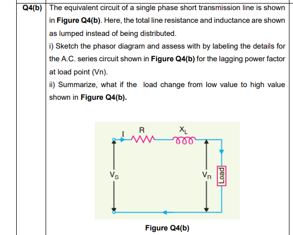
The equivalent circuit of a single phase short transmission line is shown in Figure Q4(b). Here, the total line resistance and inductance are shown as lumped instead of being distributed. i) Sketch the phasor diagram and assess with by labeling the details for the A.C. series circuit shown in Figure Q4(b) for the lagging power factor at load point (Vn). ii) Summarize, what if the load change from low value to high value shown in Figure Q4(b). R XL Vs Vn Load
The equivalent circuit of a single phase short transmission line is shown in Figure Q4(b). Here, the total line resistance and inductance are shown as lumped instead of being distributed. i) Sketch the phasor diagram and assess with by labeling the details for the A.C. series circuit shown in Figure Q4(b) for the lagging power factor at load point (Vn). ii) Summarize, what if the load change from low value to high value shown in Figure Q4(b). R XL Vs Vn Load

Power System Analysis and Design (MindTap Course List)
6th Edition
ISBN:9781305632134
Author:J. Duncan Glover, Thomas Overbye, Mulukutla S. Sarma
Publisher:J. Duncan Glover, Thomas Overbye, Mulukutla S. Sarma
Chapter4: Transmission Line Parameters
Section: Chapter Questions
Problem 4.27P: Figure 4.34 shows double-circuit conductors' relative positions in segment I of transposition of a...

Related questions

Question
Transcribed Image Text:Q4(b) The equivalent circuit of a single phase short transmission line is shown
in Figure Q4(b). Here, the total line resistance and inductance are shown
as lumped instead of being distributed.
i) Sketch the phasor diagram and assess with by labeling the details for
the A.C. series circuit shown in Figure Q4(b) for the lagging power factor
at load point (Vn).
ii) Summarize, what if the load change from low value to high value
shown in Figure Q4(b).
R
XL
el
Vs
Vn
Figure Q4(b)
Load
Expert Solution
This question has been solved!
Explore an expertly crafted, step-by-step solution for a thorough understanding of key concepts.

This is a popular solution!

Trending now
This is a popular solution!

Step by step
Solved in 3 steps with 4 images

Knowledge Booster


Learn more about
Need a deep-dive on the concept behind this application? Look no further. Learn more about this topic, electrical-engineering and related others by exploring similar questions and additional content below.Recommended textbooks for you
Power System Analysis and Design (MindTap Course …
Electrical Engineering
ISBN:
9781305632134
Author:
J. Duncan Glover, Thomas Overbye, Mulukutla S. Sarma
Publisher:
Cengage Learning
Power System Analysis and Design (MindTap Course …
Electrical Engineering
ISBN:
9781305632134
Author:
J. Duncan Glover, Thomas Overbye, Mulukutla S. Sarma
Publisher:
Cengage Learning