
Concept explainers
Videos
For the case of double-circuit, bundle-conductor lines, the same method indicated in Problem 4.27 applies with r' replaced by the bundle’s GMR in the calculation of the overall GMR.
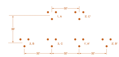
Now consider a double-circuit configuration shown in Figure 4.36 that belongs to a 500-kV, three-phase line with bundle conductors of three subconductors at 21 in. spacing. The GMR of each subconductor is given to be 0.0485 ft.
Determine the inductive reactance of the line in ohms per mile per phase. You may use

Trending nowThis is a popular solution!

Chapter 4 Solutions
Power System Analysis and Design (MindTap Course List)


- The capacitance of a single-circuit, three-phase transposed line with the configuration shown in Figure 4.38, including ground effect, and with conductors not equilaterally spaced is given by C20lnDeqrlnHmH8 F/m line-to-neutral where Deq=D12D23D133=GMD r= conductors outside radiusHm=(H12H23H13)1/3HS=(H1H2H3)1/3 Now consider Figure 4.39 in which the configuration of a three-phase, single circuit, 345-kV line with conductors having an outside diameter of 1.065 in. is shown. Determine the capacitance to neutral in F/m, including the ground effect. Next, neglecting the effect of ground, see how the value changes.arrow_forwardTransmission line conductance is usually neglected in power system studies. True Falsearrow_forwardFor either single-phase two-wire line or balanced three-phase three-wire line with equal phase spacing D and with conductor radius r, the capacitance (line-to-neutral) in F/m is given by Can=.arrow_forward
- For a completely transposed three-phase line identical conductors, each with GMR denoted DS with conductor distance D12,D23, and D31 give expressions for GMD between phases and the average per-phase inductance.arrow_forwardThree ACSR Drake conductors are used for a three-phase overhead transmission line operating at 60 Hz. The conductor configuration is in the form of an isosceles triangle with sides of 20, 20, and 38 ft. (a) Find the capacitance-to-neutral and capacitive reactance-to-neutral for each 1-mile length of line. (b) For a line length of 175 mi and a normal operating voltage of 220 kV, determine the capacitive reactance-to-neutral for the entire line length as well as the charging current per mile and total three-phase reactive power supplied by the line capacitance.arrow_forwardWhat are the parameters need to consider for transmission line, explain in basic terms?arrow_forward
- How will you ensure minimum cost for the generation of required power for a given load? You may neglect transmission line losses. Support with mathematical formulationsarrow_forwardPlease answer in short and dont copy i will like.... A. For underground and underwater transmission, why are line losses for HVDC cables lower than those of ac cables with similar capacity? B. What are the benefits of controlling of power flows on individual lines? What are the risks?arrow_forwardQ1: a) Discuss the effect of earth on the capacitance of a line : b) Derive in expression for the capacitance to neutral per phase per Km of a single phase overhead transmission line, taking into account the effect of earth. c) Derive in expression for the capacitance to neutral per phase per Km of a 3- phase overhead transmission line when conductors are of equilateral spacing.arrow_forward
- Compare Equivalent- π and Nominal-π in transmission lines. What are their diffirences? When we use them, in order to do what ?Thank youarrow_forwardIn terms of cable performance, what are the effects of temperature fluctuations on transmission cabling?arrow_forwardDiscuss three negative effects that result from the effects of the construction of a transmission line (during its construction and after)arrow_forward
 Power System Analysis and Design (MindTap Course ...Electrical EngineeringISBN:9781305632134Author:J. Duncan Glover, Thomas Overbye, Mulukutla S. SarmaPublisher:Cengage Learning