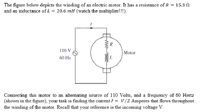
The figure below depicts the winding of an electric motor. It has a resistance of R = 15.3 and an inductance of L = 20.6 mH (watch the multiplier!!!). 110 V 60 Hz. www R Motor Connecting this motor to an alternating source of 110 Volts, and a frequency of 60 Hertz (shown in the figure), your task is finding the current = V/Z Amperes that flows throughout the winding of the motor. Recall that your reference is the incoming voltage V.


Q: 5.49 For the circuit in Fig. P5.49, determine i₁ (t) and plot it as a function of t for t≥ 0. The…
A: An inductor is a passive electrical component that stores energy in the form of a magnetic field…
Q: In the DeviceNet network below, what is the address of a barcode scanner connected to Port 5 of the…
A: The given image is shown below.
Q: 7 and 8 please I will like
A: Please see the attached image for an answerExplanation:
Q: Q3) Twenty voice signals are sampled uniformly and then time division multiplexed. The sampling…
A: The lowest sample rate needed to accurately represent a signal without aliasing is known as the…
Q: 5. A 25 MVA turbo-alternator is working on full load at a power factor of 0-8 and efficiency of 97%.…
A: Given data S = 25 MVA pf = 0.8 efficiency = 97% loss by internally circulating air =90 % of total…
Q: 3.3
A: Final answer and explanation are in the explanation part.Explanation: Please let me know if there…
Q: Solve the following circuit for I. using. Nodal Analysis. 212 w HV F ΙΚΩ ↑ 12 MA ↓。
A: Given:we need to determine the current I0 using nodal analysis.
Q: Problem 3: angle modulation) (a) The message m(t) and the FM-modulated signal u(t) are both given on…
A: The final answer is : a) To find the maximum frequency deviation, identify the peak difference…
Q: Compute the power absorbed or supplied by each element of the circuit below 9 A 2 V I=5A 5V + P2 P1…
A: Given circuit is,Asked to find the power absorbed (or) delivered by each element.
Q: A three-phase generator made in the US (60-Hz frequency) has an internal voltage of 120 V at rated…
A:
Q: Identify the placement of a mercury lamp light source relative to the Pasco interferometer in Figure…
A: Please follow the User's Instruction Manual of PASCO Interferometer. A LASER, followed by a beam…
Q: The figure displays two circuits with a charged capacitor that is to be discharged through a…
A:
Q: A wire carrying a current /= 27.0 A is bent into the shape of an exponential spiral. Its polar…
A: This is a electric field
Q: Problem 2.33. Readings of the ammeter and voltmeter are shown in the following figure. A. Based on…
A: In he the given questions we need to analyse that unknown element is resistance or current source
Q: Current Attempt in Progress What are the (a) magnitude and (b) direction (up or down) of current i…
A: The given circuit isThe value of each resistance is ⇒R=5.4 Ω.The emf of each battery (i.e of ideal )…
Q: What kVA rating is required for a transformer that must handle a maximum load current of 8 A with a…
A: GIven the maximum load current and secondary voltage and required to find the kVA rating.
Q: please answer question 11 !!! thanks !!!
A: FINAL ANSWER:- When the circular fringes collapsing to the centre then the mirror spacing is…
Q: 1.24 The voltage across a element varies with time as 5(t-2)² V. A current of 2 A enters the +ve…
A: In this question, we need to determine the power delivered to the element at time t=0.8s.
Q: Suppose the negative terminals of Vin and Vout in Fig. 3.38(b) are shorted together. Plot the…
A: In the given question we need to plot the input and output waveform of the given diode circuit.
Q: 4.23. A 320-kVA, 240/4800-V, 60-Hz transformer yielded the following infor- mation when tested:…
A:
Q: If you double the impedance of a transmission line you will double the inductance per unit length. T…
A: Given statement is false Explanation:
Q: Show all of you work and each steps please. Also if you could write down the formulas you used, that…
A: In this problem the given equivalent circuit :and In this problem we applied kirchhoff's voltage law…
Q: B + จง R www чи Vout (+)
A:
Q: 32. 4.32 Implement the following Boolean function with a multiplexe 1. (a) F (A, B, C, D)=(0, 2, 5,…
A: Here we have boolean function and asked to implement the function using multiplexer.
Q: 2 I 1 ala R₂ w V☹ R₁ 0 www R3 7 6 A Ia B 5 3 Determine the voltage drop (in volts) from A to B for…
A: Here we have to find the voltage drop from A to B for the given circuit.
Q: 3. A source of information produces equaiprobable blocks of 4-bits. The encoder circuit adds an even…
A: The input-output relationship of an encoder circuit is represented by an encoder table. This makes…
Q: For this question, I just need to understand if the analogy is a Multiplexer, Demultiplexer,…
A:
Q: 5) Determine and plot the real continuous-time signal x(t) if its magnitude and phase spectra are as…
A: Given:magnitude and phase spectra of a continuous time signal x(t),we need to find and plot the…
Q: 7-2) Similar to Lathi & Ding, Prob. P.4.8-3 A shortwave radio receiver designed to operate in the 49…
A: Given:in short wave radio, the IF is 455 kHz, a receivers is designed to receive shortwave…
Q: This is a practice question from the Signal and Systems course of my Electrical Engineering Program.…
A: These Fourier transform can be solved by two technique.1. Using Fourier transform properties which I…
Q: Find the power by the 4k ohm's resistor
A: According to questions, we need to calculate the power absorbed by 4k ohm resistor.
Q: The question is accompanied with the uploaded image:
A: a) Determine which one of the two BJTs is ON which one is OFFGiven an input voltage of -5V:For Q1 to…
Q: Make Diagram For the Below Details 1. Pump (12v 110psi max pressure) 2. Battery (12V 8Ah) 3. On/off…
A: Given parameters to draw diagram
Q: only part d
A: Dopant freezing is a phenomenon that occurs in heavily doped semiconductor materials at low…
Q: Can you show the circuit for this or the diagram?
A:
Q: Please answer in typing format
A: The circuit diagram,
Q: Find the value of C, in μF, if the energy stored in the capacitor in Fig.P6.28 equals the energy…
A: energy stored in the capacitor is equal to the energy stored in the inductor.
Q: - 7. Show the result of sin(wt – 30°) + cos(wt + 10°) in cosine format. With the use of phasor. a)…
A: Given that,The objective is to find the result of in cosine format.
Q: Find the Thevenin equivalent circuit to the left of terminals a and b. Check your answers by finding…
A: In this question, we need to determine the Thevenin equivalent circuit across the terminals a and b.…
Q: 1. The switch has been in position a for a long time. It is switched to position b at t = 0.0 s 9.0…
A: the switch has been in position a for a long time and moved to position b at t=0.
Q: Design a Single-phase bridge rectifier that is required to energize a load with (X) Watts and with…
A: Double-check component datasheets and consider factors like temperature and circuit layout for a…
Q: The flux through a toroidal magnetic material is 6 µWb, and the magnetic field intensity is 12 A/m.…
A: 19098Explanation:Step 1:
Q: In the circuit below, find: a) i₁(0+), i2(0+), diz (0+), diz (0+) dt dt -, i₁(00), i₂ (00) b) i(t),…
A: Since you have posted the questions with multiple support. And each subparts again have 6 parts. So…
Q: Q2. Select the correct answer of the following. 1. The full load voltage of transformer when…
A: In the given questions we need to select the correct option. The questions are related to the single…
Q: Solve the circuit by nodes (LCK) and find the function IR(s)/I(s) Please solve the system showing…
A:
Q: 7.21 Ignoring reflection at the air-soil boundary, if the amplitude of a 3 GHz incident wave is 10…
A: According to the question, we need to find depth.
Q: Q2\ fill in the blanks. 1- There are three types of thermistor ..... and
A: Since you have posted multiple questions, we will provide the solution only to the first question as…
Q: Could you explain the solution a little bit better?
A: By using Fourier Transform properties we can obtain Y2(f) =0 and y2(t) =0. Explanation:Step 1:Step…
Q: A flow meter sensor is connected to the microcontroller card to convert the signal and display it as…
A: In industrial processes the measurement of fluid flow rates is very important.The utilization of…
Q: 1. 4.1 Consider the combinational circuit shown in Fig. P4.1. (HDL- see Problem 4.49) A B C D T3 F₁…
A: The required Boolean expression can be obtained by using the logic diagram and the same can be…

Unlock instant AI solutions
Tap the button
to generate a solution
Click the button to generate
a solution
- A series circuit consisting of a resistor that dissipates 640watts, a coil and an ideal capacitor is connected across a 220volts, 60Hz power supply. The current drawn by the load is 8 amperes. The voltage across the coil is 150 volts and its power factor is 0.8 lagging. Determine: a. the resistance of the resistor (10 Ohms)b. the resistance and the inductance of the coil ( 15 Ohms, 29.8416 mH)c. the voltage across the capacitor (181.6515 V)d. the capacitance of the capacitor (116.8207 μF)In a purely inductive AC circuit as shown in the figure, ΔVmax = 100 V. a) The maximum current is 9.00 A at 40.0 Hz. Calculate the inductance L. b) At what angular frequency ? is the maximum current 1.50 A?If it is connected in series with a pure resistance R with resistance R, inductance L, the current it draws with sinusoidal voltage application with an effective value of 100V is 5A. The voltage at the ends of the coil and resistance element is 80V and 30V.a-find only the power and power factor spent by the coil?b-find the power and power factor that the system consumes?c-draw the voltage triangle, impedance triangle and power triangle? Can you solve the all a, b and c options? Please
- When it is connected in series with a pure resistor R with resistance r and inductance L, the current it draws with a sinusoidal voltage application with an effective value of 100V is 5A. The voltage across the coil and resistor element is 80V and 30V. a-Find the power and power factor consumed by the coil alone? b- Find the power consumed by the system and the power factor? c- Draw the voltage triangle, impedance triangle and power triangle?1. With a neat sketch briefly explain how an alternating voltage is produced when a coil is rotated in a magneticfield. 2. Derive expressions for average value and RMS value of a sinusoidally varying AC voltage 3. A circuit having a resistance of 12Ω, an inductance of 0.15 H and a capacitance of 100μf in series is connectedacross a 100V, 50Hz supply. Calculate the impedance, current, the phase difference between the current andsupply voltage. 4. Two circuits with impedances of Z1 = 10 + j15Ω and Z2 = 6 – j8Ω are connected in parallel. If the supply current is 20A, what is the power dissipated in each branch?An RLC series circuit connected to a 110 – volt and 50 – cycle AC source, contains the following series resistances and reactances: R1 = 10 ohm, R2 = 15, R3 = 5 ohms, XL1 = 20 ohms, XL2 = 25 ohms, XC = 40 ohms. Find the following: a.) EQUIVALENT REACTANCE b.) TOTAL IMPEDANCE c.) VOLTAGE DROP ACROSS THE CAPACITOR d.) TOTAL INDUCTANCE IN MILLIHENRY e.) TOTAL CURRENT f.) REACTIVE POWER g.) REAL POWER DRAW THE PHASOR DIAGRAM IF POSSIBLE AND ROUND OFF TO FOUR DECIMAL PLACES
- A motor with 1mH of inductance and an unknown internal resistance is connected to a 100V RMS 10kHz source. The power factor has been corrected by adding a 247nF capacitor in parallel with the motor. Calculate the value of the internal resistance.You are given five light bulbs designed to operate on 160 mA current at 3.0 V (rms values), arid want to connect them in parallel, through an ideal transformer, to 120 V rms AC household power. a) Draw a circuit diagram showing the AC power source (a generator symbol ), the transformer, and resistors for the light bulbs. b) Is the required transformer step-up or step-down? What turns ratio N5/N is needed? e) Calculate the ruts current through both the primary and secondary coils of the trans former, in mA.1- When connected in series with a pure resistor R with resistance r and inductance L, three pairs of currents are 5A with a sinusoidal voltage application with an effective value of 100V. The voltage across the coil and resistor element is 80V and 30V. a-Find the power and power consumed by the coil alone? b- Find the power consumed by the system and the power factor? c- Draw the voltage triangle, impedance triangle and power triangle?
- The impedance coil absorbs 250 watts when connected across 220 V, 60 Hz mains, it is then connected across 110 V, 25 Hz mains and also absorbs 250 watts. What is the inductance of the coil? Show complete solution.A four pole lap one armature running at 1500 RPM delivers a current of 150 amperes and has a 64 commuter segments. The brush spans 1.2 segments and inductance of each armature coil is 0.05 mH. Calculate the value of reactance voltage assuming (i) linear communication (ii) sinusoidal commutation. Neglect Mica thickness. (Our subject is ELECTRICAL MACHINE 1)An inductive coil and a non-inductive resistance R ohms are connected in series across an a.c. supply. Deriveexpressions for the power taken by the coil and its power factor in terms of the voltage across the coil, theresistance and the supply respectively. If R = 12 Ω and the three voltages are in order, 110 V, 180 V and 240 V,calculate the power and the power factor of the coil.