The figure illustrates the non-permanent connection of a steel cylinder head to a grade 30 cast- iron pressure vessel using N bolts. A confined gasket seal has an effective sealing diameter D. The cylinder stores gas at a maximum pressure p, For the specifications given in the table for the specific problem assigned, select a suitable bolt length from the preferred sizes in , then determine the yielding factor of safety n. the load factor n, and the joint actor n
The figure illustrates the non-permanent connection of a steel cylinder head to a grade 30 cast- iron pressure vessel using N bolts. A confined gasket seal has an effective sealing diameter D. The cylinder stores gas at a maximum pressure p, For the specifications given in the table for the specific problem assigned, select a suitable bolt length from the preferred sizes in , then determine the yielding factor of safety n. the load factor n, and the joint actor n

Mechanics of Materials (MindTap Course List)
9th Edition
ISBN:9781337093347
Author:Barry J. Goodno, James M. Gere
Publisher:Barry J. Goodno, James M. Gere
Chapter1: Tension, Compression, And Shear
Section: Chapter Questions
Problem 1.9.9P: A lifeboat hangs from two ship's davits. as shown in the figure. A pin of diameter d = 0.80 in....

Related questions

Question
100%
The figure illustrates the non-permanent connection of a steel cylinder head to a grade 30 cast- 8-35 iron pressure vessel us
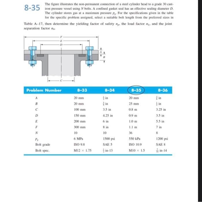
Transcribed Image Text:The figure illustrates the non-permanent connection of a steel cylinder head to a grade 30 cast-
iron pressure vessel using N bolts. A confined gasket seal has an effective sealing diameter D.
The cylinder stores gas at a maximum pressure P For the specifications given in the table
for the specific problem assigned, select a suitable bolt length from the preferred sizes in
Table A-17, then determine the yielding factor of safety n the load factor n, and the joint
8-35
separation factor no-
Problem Number
8-33
8-34
8-35
8-36
u f
in
20 mm
20 mm
in
I in
B
20 mm
25 mm
3.5 in
0.8 m
100 mm
3.25 in
D
150 mm
4.25 in
0.9 m
3.5 in
200 mm
6 in
10 m
5.5 in
300 mm
8 in
1.I m
7 in
10
10
36
8
6 MPa
1500 psi
550 kPa
1200 psi
ISO 10.9
MI0 x 1.5
Bolt grade
ISO 9.8
SAE S
SAE 8
Bolt spec.
M12 x 1.75
in-13
is in-14
Expert Solution
This question has been solved!
Explore an expertly crafted, step-by-step solution for a thorough understanding of key concepts.

This is a popular solution!

Trending now
This is a popular solution!

Step by step
Solved in 2 steps with 2 images

Knowledge Booster


Learn more about
Need a deep-dive on the concept behind this application? Look no further. Learn more about this topic, mechanical-engineering and related others by exploring similar questions and additional content below.Recommended textbooks for you
Mechanics of Materials (MindTap Course List)
Mechanical Engineering
ISBN:
9781337093347
Author:
Barry J. Goodno, James M. Gere
Publisher:
Cengage Learning
Mechanics of Materials (MindTap Course List)
Mechanical Engineering
ISBN:
9781337093347
Author:
Barry J. Goodno, James M. Gere
Publisher:
Cengage Learning