The Figure shown below is a parallel pipeline system with two branches used to supply lubricating water to the bearings. The main line and two branches use the same size of pipes. The pressures at section 1 and section 2 are p₁=398.1kPa and p₂=300kPa , respectively. The resistance coefficients for two bearings are K₁=5 and K₂=12. The cross section areas of two branch pipes are A = A=1.5x 10⁻⁴m². The energy loss caused by friction can be ignored. The energy loss caused by one bend is h₂=0.2 m. (8) Calculate the velocity v in branch b K₁ K₂ m/s (P₂
The Figure shown below is a parallel pipeline system with two branches used to supply lubricating water to the bearings. The main line and two branches use the same size of pipes. The pressures at section 1 and section 2 are p₁=398.1kPa and p₂=300kPa , respectively. The resistance coefficients for two bearings are K₁=5 and K₂=12. The cross section areas of two branch pipes are A = A=1.5x 10⁻⁴m². The energy loss caused by friction can be ignored. The energy loss caused by one bend is h₂=0.2 m. (8) Calculate the velocity v in branch b K₁ K₂ m/s (P₂

Elements Of Electromagnetics
7th Edition
ISBN:9780190698614
Author:Sadiku, Matthew N. O.
Publisher:Sadiku, Matthew N. O.
ChapterMA: Math Assessment
Section: Chapter Questions
Problem 1.1MA

Related questions
Question
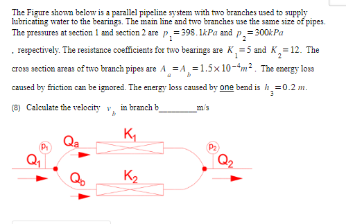
The Figure shown below is a parallel pipeline system with two branches used to supply lubricating water to the bearings. The main line and two branches use the same size of pipes. The pressures at section 1 and section 2 are and , respectively. The resistance coefficients for two bearings are and . The cross section areas of two branch pipes are . The energy loss caused by friction can be ignored. The energy loss caused by one bend is .
(8) Calculate the velocity in branch b_________m/s
Transcribed Image Text:The Figure shown below is a parallel pipeline system with two branches used to supply
lubricating water to the bearings. The main line and two branches use the same size of pipes.
The pressures at section 1 and section 2 are p₁=398.1kPa and p₂=3
= 300kPa
, respectively. The resistance coefficients for two bearings are K₁₂=5 and K₂=12. The
1
b
cross section areas of two branch pipes are A = A=1.5x 10⁻⁴m². The energy loss
caused by friction can be ignored. The energy loss caused by one bend is h₂=0.2 m.
3
(8) Calculate the velocity v in branch b
K₁
K₂
m/s
Expert Solution
This question has been solved!
Explore an expertly crafted, step-by-step solution for a thorough understanding of key concepts.

This is a popular solution!

Trending now
This is a popular solution!

Step by step
Solved in 2 steps with 3 images

Knowledge Booster


Learn more about
Need a deep-dive on the concept behind this application? Look no further. Learn more about this topic, mechanical-engineering and related others by exploring similar questions and additional content below.Recommended textbooks for you
Elements Of Electromagnetics
Mechanical Engineering
ISBN:
9780190698614
Author:
Sadiku, Matthew N. O.
Publisher:
Oxford University Press

Mechanics of Materials (10th Edition)
Mechanical Engineering
ISBN:
9780134319650
Author:
Russell C. Hibbeler
Publisher:
PEARSON

Thermodynamics: An Engineering Approach
Mechanical Engineering
ISBN:
9781259822674
Author:
Yunus A. Cengel Dr., Michael A. Boles
Publisher:
McGraw-Hill Education
Elements Of Electromagnetics
Mechanical Engineering
ISBN:
9780190698614
Author:
Sadiku, Matthew N. O.
Publisher:
Oxford University Press
Mechanics of Materials (10th Edition)
Mechanical Engineering
ISBN:
9780134319650
Author:
Russell C. Hibbeler
Publisher:
PEARSON
Thermodynamics: An Engineering Approach
Mechanical Engineering
ISBN:
9781259822674
Author:
Yunus A. Cengel Dr., Michael A. Boles
Publisher:
McGraw-Hill Education

Control Systems Engineering
Mechanical Engineering
ISBN:
9781118170519
Author:
Norman S. Nise
Publisher:
WILEY

Mechanics of Materials (MindTap Course List)
Mechanical Engineering
ISBN:
9781337093347
Author:
Barry J. Goodno, James M. Gere
Publisher:
Cengage Learning

Engineering Mechanics: Statics
Mechanical Engineering
ISBN:
9781118807330
Author:
James L. Meriam, L. G. Kraige, J. N. Bolton
Publisher:
WILEY