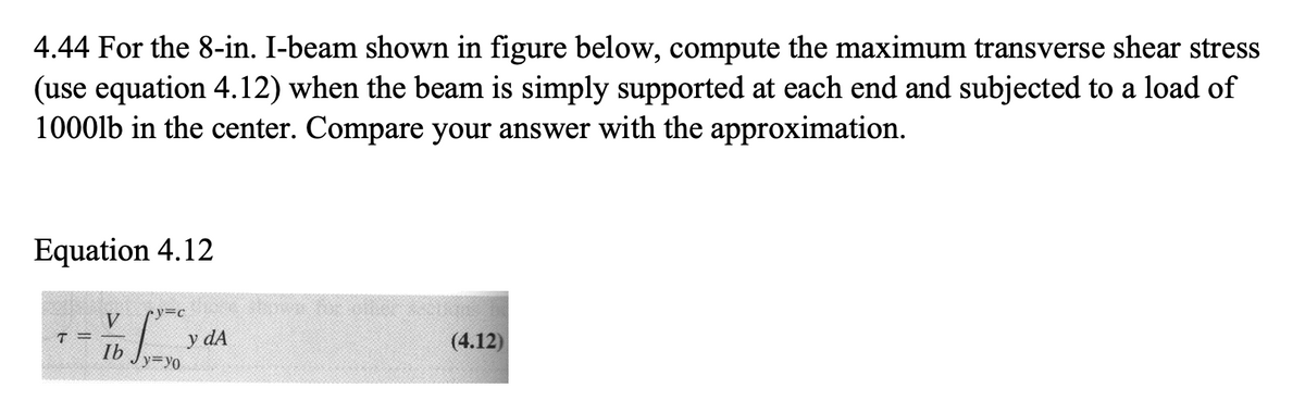
4.44 For the 8-in. I-beam shown in figure below, compute the maximum transverse shear stress (use equation 4.12) when the beam is simply supported at each end and subjected to a load of 1000lb in the center. Compare your answer with the approximation.
4.44 For the 8-in. I-beam shown in figure below, compute the maximum transverse shear stress (use equation 4.12) when the beam is simply supported at each end and subjected to a load of 1000lb in the center. Compare your answer with the approximation.

Mechanics of Materials (MindTap Course List)
9th Edition
ISBN:9781337093347
Author:Barry J. Goodno, James M. Gere
Publisher:Barry J. Goodno, James M. Gere
Chapter4: Shear Forces And Bending Moments
Section: Chapter Questions
Problem 4.3.13P: Beam ABCD represents a reinforced-concrete foundation beam that supports a uniform load of intensity...

Related questions
Question
Pls help with detailed steps. Dont copy from anywhere. I want to understand the process please. Thanks!
Transcribed Image Text:4.44 For the 8-in. I-beam shown in figure below, compute the maximum transverse shear stress
(use equation 4.12) when the beam is simply supported at each end and subjected to a load of
1000lb in the center. Compare your answer with the approximation.
Equation 4.12
ソ=c
V
y dA
(4.12)
Ib
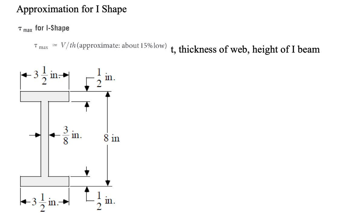
Transcribed Image Text:Approximation for I Shape
for l-Shape
max
T
max
V/th (approximate: about 15% low)
t, thickness of web, height of I beam
1
in.
2
3
in:
3
in.
8 in
in.
H N
Expert Solution
This question has been solved!
Explore an expertly crafted, step-by-step solution for a thorough understanding of key concepts.

This is a popular solution!

Trending now
This is a popular solution!

Step by step
Solved in 3 steps with 3 images

Knowledge Booster


Learn more about
Need a deep-dive on the concept behind this application? Look no further. Learn more about this topic, mechanical-engineering and related others by exploring similar questions and additional content below.Recommended textbooks for you
Mechanics of Materials (MindTap Course List)
Mechanical Engineering
ISBN:
9781337093347
Author:
Barry J. Goodno, James M. Gere
Publisher:
Cengage Learning
Mechanics of Materials (MindTap Course List)
Mechanical Engineering
ISBN:
9781337093347
Author:
Barry J. Goodno, James M. Gere
Publisher:
Cengage Learning