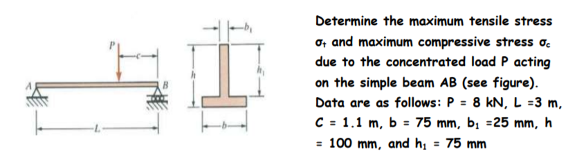
Determine the maximum tensile stress o, and maximum compressive stress o. due to the concentrated load P acting on the simple beam AB (see figure). Data are as follows: P = 8 kN, L =3 m C = 1.1 m, b = 75 mm, bị =25 mm, h = 100 mm. and h. = 75 mm
Q: A cantilever beam of length L= 1 m supports a load P = 8 kN, shown in figure. The beam is made of…
A:
Q: Problem C-3 [Beam Bending - Normal Stress] A simply supported beam (i.e., with a pin support at…
A:
Q: In the figure, find the length c of the overhangs so that the beam made of U profile can carry the…
A:
Q: A ec=K L B b→,K 1. (Section)
A:
Q: 10 kN 3 kN/m 100 mm 200 mm B 1.5 m 1.5 m 2.2 m
A:
Q: 4.44 For the 8-in. I-beam shown in figure below, compute the maximum transverse shear stress (use…
A: First let us determine the moment of inertia of the section Moment of inertia about neutral axis =…
Q: Q1: The horizontal rigid beam ABCD is supported by vertical bars BE and CF and is loaded by vertical…
A:
Q: (6) For the composite beam shown in the figure, which is bended about a horizontal axis by a couple…
A:
Q: Q.2 A square timber beam used as a railroad tie is supported by a uniformly distributed loads and…
A: From the above diagram- Maximum stress limited=8 mPa
Q: A simple beam is loaded as shown in the figure below If the load P 120 kN determine the maximum…
A: Normal stress will be maximum at cross section 'B'Net normal stress = Normal stressaxial+Normal…
Q: For the cantilever beam with uniformly distributed load shown in Figure find: d. The moment of…
A: Consider the given cantilever beam. Calculate the reaction at the fixed end. R=16 kN/m5 mR=80 kN…
Q: In the figure, find the length c of the overhangs so that the beam made of U profile can carry the…
A:
Q: A cantilever beam with length, L = 5 m, is supporting a downward concentrated load, P = 88 kN, at…
A:
Q: (c) If the uniform axial centroidal load q = 18.33 kN/m is applied to the left over segment 1 (see…
A: Part (c) I will explain the whole process. The integration is not mandatory. We can use the direct…
Q: The composite beam in the figure is made of steel and aluminum. Beam In steel and aluminum as it is…
A: Given: Esteel=210GPa Eal=70GPa M=2kNm Solution: The position of the neutral axix is exactly at the…
Q: applied to the beam in the figure with the notches below and a hole of diameter d in the middle.…
A:
Q: Consider a wood beam (see figure) carrying a uniform load of 13.5 kN/m (which includes the weight of…
A: In this part, each part is having 2 unknowns so we will solve first part for you. Please resubmit…
Q: A horizontal beam AB with cross-sectional dimensions (b = 0.75 in.) X (h = 8.0 in.) is supported by…
A:
Q: A simply supported beam (i.e., with a pin support at point A and a roller support at point D) is…
A:
Q: The figure shows a rectangular section beam with a distributed load of 3 KN/m. Decide: The maximum…
A: Consider a beam having Area Moment of Inertia I and Young's modulus E is subjected to bending moment…
Q: A curved frame ABC is fixed at one end and subjected to a concentrated load P, as shown in Figure.…
A: →For section AB(0≤x≤L):-Mx=PxMx=0=MA=0Mx=L=MB=PL →For section BC:- Equation of moment at an angle…
Q: A beam AB, 3 m long is hinged to a wall at end A and is supported by a tie rod DE which is hinged to…
A: Draw sketch of beam Determine angle of tie rod from horizontal
Q: Problem 6.4-6 A wood cantilever beam of rectangular cross section and length L supports an inclined…
A: Given Data b=80 mm h=140 mm L=2.0 m P=575 N α=30o Calculating bending moment about y-axiz…
Q: Ex: For a simple beam of length (L) subject to a concentrated load (P), shown in figure, Find : 1.…
A: Since, all the three parts are different question. And, as per the guidelines, I can solve only one…
Q: Q1: The horizontal rigid beam ABCD is supported by vertical bars BE and CF and is loaded by vertical…
A:
Q: 5.8-7A steel beam of length L = 16 in. and cross- sectional dimensions b = 0.6 in. and h = 2 in.…
A: Explanation: The stepwise procedure to solve this problem is shown in the following attached image:
Q: The rigid beam BC shown in Figure is supported by rods (1) and (2) that have cross-sectional areas…
A: Given data: A1=175 mm2A2=300 mm2w=15 kN/mL=3 ma=1.8 m Need to determine the stress in each bar.
Q: A cantilever beam of rectangular cross section is subjected to a concentrated load P = 150 kN acting…
A:
Q: Ahorizontal beam AB with cross-sectional dimensions 4 ft -5 ft Ab # 075 in.)X h#8.0 in. is supported…
A:
Q: In the beam loading system given below, A is a simple and C is a sliding support. The outer diameter…
A:
Q: Q1 A cantilever beam AB of isosceles trapezoidal cross section has length L = 0.8 m, dimension bi =…
A: For solution refer below images.
Q: The horizontal beam AB of 1.8-2 cross-sectional dimensions (b x h = 19 mm x 200 mm) is supported by…
A:
Q: A horizontal beam AB of 1.8-2 cross-sectional dimensions (b X h = 19 mm x 200 mm) is supported by an…
A:
Q: Q.2 A square timber beam used as a railroad tie is supported by a uniformly distributed loads and…
A: Given: ununiform distributed load→W1=24 KN and W2=48 KN Hence upward uniform distributed load:…
Q: A cantilever beam of rectangular cross section is subjected to a concentrated load P = 150 kN acting…
A:
Q: A column with a wide-flange section has a flange width b = 200 mm , height h = 200 mm , web…
A:
Q: A composite beam is made of two brass [E =101 GPa] plates bonded to an aluminum [E =64 GPa] bar, as…
A:
Q: Horizontal beam ACB with cross section dimensions (width = b) (height = h) as shown in the figure…
A: (a) Consider the free body diagram of the given figure as shown below.
Q: Calculate the maximum shear stress o h, 10.1 in., and the shear force V = 4,700 Ib. (Enter the…
A: Givenb=14int=0.5inh=11inh1=10.1inV=4700lb
Q: In the figure, aluminum [E = 75 GPa] links (1) and (2) support rigid beam ABC. Link (1) has a…
A: Consider a bar having cross-sectional area A,Length L and Young's Modulus E is subjected to axial…
Q: In the Figure below, a cantilever beam is subjected to an inclined force (P); calculate the: 1-…
A:
Q: The hollow circle cross section of the simply supported beam shown in the figure. Find the maximum…
A: For solution refer below images.
Q: Q: For the cantilever beam with uniformly distributed load shown in Figure find; a The maximum shear…
A: As per company policy, we are restricted to solve only the first three sub-part of one question at a…
Q: A flat bar of rectangular cross section, length L, and constant thickness tis subjected to tension…
A:
Q: A circular cross-section Beam has a simple headstock from the ends, as shown in the figure, Q is…
A:
Q: A bimetallic beam used in a temperature-control switch consists of strips of aluminum and coppe…
A:
Q: please answer the question
A: MAB=-400×108=-500 kN-mMBA=500 kN-mMBC=30×10212=30×10012=-250 kN-mMCB=250 kN-m
Q: Determine the maximum tensile stress er and maximum compressive stress ec due to the load P acting…
A:
Q: * The hollow circle cross section of the simply supported beam shown in the figure. Find the maximum…
A: For solution refer below images.
Trending now
This is a popular solution!
Step by step
Solved in 3 steps with 1 images
- A simple beam of span length 3.2 m carries a uniform load of intensity 48 kN/m, The cross section of the beam is a hollow box with wood flanges and steel side plates, as shown in the figure. The wood flanges are 75 mm x 100 mm in cross section, and the steel plates are 300 mm deep. What is the required thickness t of the steel plates if the allowable stresses are 120 M Pa for the steel and 6,5 M Pa for the wood? (Assume that the moduli of elasticity for the steel and wood are 210 GPa and 10 GPa, respectively, and disregard the weight of the beam.)A simple beam that is 18 ft long supports a uniform load of intensity q. The beam is constructed of two C8 x 11.5 sections (channel sections or C-shapes) on either side of a 4 × 8 (actual dimensions) wood beam (see the cross section shown in the figure part a). The modulus of elasticity of the steel (E; = 30,000 ksi) is 20 times that of the wood (Ew). (a) If the allowable stresses in the steel and wood are 12,000 psi and 900 psi, respectively, what is the allowable load qmax Note: Disregard the weight of the beam, and see Table F-3(a) of Appendix F for the dimensions and properties of the C-shape beam. (b) If the beam is rotated 90° to bend about its v axis (see figure part b) and uniform load q = 250 lb/ft is applied, find the maximum stresses trs and crw in the steel and wood, respectively Include the weight of the beam. (Assume weight densities of 35 lb/ft3 and 490 lb/ft3 for the wood and steel, respectively.)A bimetallic beam used in a temperature-control switch consists of strips of aluminum and copper bonded together as shown in the figure, which is a cross-sectional view. The width of the beam is LO in,, and each strip has a thickness of 1/16 in. Under the action of a bending moment M = 12 lb-in, acting about the z axis, what are the maximum stresses aaand ecin the aluminum and copper, respectively? (Assume fA, = 10,5 x l0 psi and ecu= 16,8 × 10⁶ psi,)
- A W 12 X 14 wide-flange beam (see Table F-l(a), Appendix F) is simply supported with a span length of 120 in. (see figure). The beam supports two anti-symmetrically placed concentrated loads of 7,5 kips each. At a cross section located 20 in. from the right-hand support, determine the principal stresses (7]and (7\ and the maximum shear stress Tmaw at each of the following locations: (a) the top of the beam, (b) the top of the web, and (c) the neutral axis,A W 200 x 41.7 wide-flange beam (see Table F-l(b), Appendix F) is simply supported with a span length of 2.5 m (see figure). The beam supports a concentrated load of 100 kN at 0.9 m from support B. At a cross section located 0,7 m from the left-hand support, determine the principal stresses tr, and 2and the maximum shear stress rnMJt at each of the following locations: (a) the top of the beam, (b) the top of the web, and (c) the neutral axis,A weight W = 4500 lb falls from a height h onto a vertical wood pole having length L = 15 ft, diameter d = 12 in., and modulus of elasticity E = 1.6 × 10⁶ psi (see figure). If the allowable stress in the wood under an impact load is 2500 psi. what is the maximum permissible height h?
- A beam with a semicircular cross section of radius r is subjected to a bending moment M having its vector at an angle 9 to the z axis (see figure). Derive formulas for the maximum tensile stress tcand the maximum compressive stress tc in the beam for 0 = 0,45º and 90º, Express the results in the form or A/r where a is a numerical value.A canti lever beam A B of a n isosceles t rapezoi-dal cross section has a length L = 0.8 m, dimensions bx= 80 mm and b2= 90 mm, and height h = 110 mm (see figure). The beam is made of brass weighing 85 kN/m3. Determine the maximum tensile stress asand maximum compressive stressA cantilever beam of W 12 × 14 section and length L = 9 ft supports a slightly inclined load P = 500 lb at the free end (see figure). Plot a graph of the stress o 4at point A as a function of the angle of inclination or Plot a graph of the angle L/3, which locates the neutral axis ma as a function of the angle a. (When plotting the graphs, let a vary from 0 to 10º) See Table F-1(a) of Appendix F for the dimensions and properties of the beam.
- A beam with a channel section is subjected to a bending moment M having its vector at an angle 0 to the 2 axis (see figure). Determine the orientation of the neutral axis and calculate the maximum tensile stress et and maximum compressive stress ecin the beam. Use the following data: C 8 × 11.5 section, M = 20 kip-in., tan0=l/3. See Table F-3(a) of Appendix F for the dimensions and properties of the channel section.A cantilever beam(Z, = 6 ft) with a rectangular cross section (/> = 3.5 in., h = 12 in.) supports an upward load P = 35 kips at its free end. (a) Find the state of stress ((7T, o^., and r in ksi) on a plane-stress element at L/2 that is i/ = 8 in. up from the bottom of the beam. Find the principal normal stresses and maximum shear stress. Show these stresses on sketches of properly oriented elements. (b) Repeat part (a) if an axial compressive centroidal load N = 40 kips is added at BBeam ABCD represents a reinforced-concrete foundation beam that supports a uniform load of intensity q1= 3500 lb/ft (see figure). Assume that the soil pressure on the underside of the beam is uniformly distributed with intensity q2 Find the shear force VBand bending moment MBat point B. Find the shear force Vmand bending moment M at the midpoint of the beam.