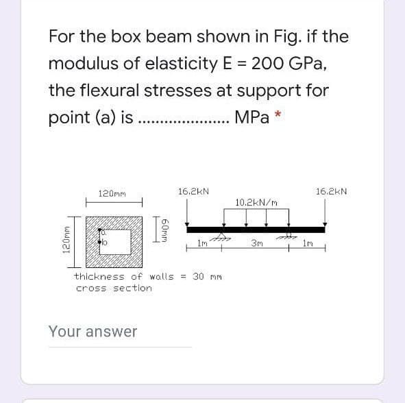
For the box beam shown in Fig. if the modulus of elasticity E 200 GPa, the flexural stresses at support for point (a) is . MPa 120mm 16.2KN 16.2KN 10.2kN/m 1m 3m im thickness of walls = 30 mm cross section 60mm 120mm


Q: For the box beam shown in Fig. if the modulus of elasticity E = 200 GPa, the flexural stresses at…
A:
Q: A simply supported beam carries a concentrated load at the center which fluctuates from a value of W…
A:
Q: In the figure, find the length c of the overhangs so that the beam made of U profile can carry the…
A:
Q: A beam carries a uniform distributed load of intensity w in N/m. It was determined that Vmax = 3.75w…
A: Note:- As per our company guidelines we are supposed to answer only the first three sub-parts.…
Q: (7) The figure shows the free body diagram of a connecting link portion having stress concentration…
A:
Q: Q3(a) A wood beam with a rectangular section is found to have the insufficient load capacity. So an…
A: according to the given details
Q: 3. A round shaft, 45 mm in diameter, carries a 3500 N load, as shown in the Figure. If the shaft is…
A:
Q: A steel cantilever beam with a 1-in-diameter round cross section and length of 10 in is loaded at…
A: Given data:
Q: 3. Find the ratio of crippling loads by Euler's and Rankine's formulae for a hollow strut of 40 mm…
A: d0=40 mm di=30 mm I=π64404-304I=85902.924 mm4σyt=300 MpaE=200 Gpaa=17500
Q: A three-quarter ring curved beam, loaded by horizontal and vertical forces at point B, has a…
A: Draw a schematic diagram of the three-quarter curved beam.
Q: For the overhanging rolled steel beam with an American standard flange cross- section, identify…
A:
Q: (a) A steel cantilever beam with a 1-in-diameter round cross section and length of 10 in is loaded…
A: Stresses are developed in machine elements due to applied load. Machine design involves ensuring…
Q: Q.2 A square timber beam used as a railroad tie is supported by a uniformly distributed loads and…
A: From the above diagram- Maximum stress limited=8 mPa
Q: For the box beam shown in Fig. if the modulus of elasticity E = 200 GPa, the %3D flexural stresses…
A:
Q: A cast iron beam is of T-section as shown in Fig. The beam is simply supported on a span of 6 m. The…
A: Given Data:- span length=6m…
Q: A cantilever beam with length, L = 5 m, is supporting a downward concentrated load, P = 88 kN, at…
A:
Q: Determine the minimum height h of the beam shown in Figure below, if the flexu ral stress is not to…
A:
Q: the amount of collapse that will occur at the B point is 4mm. The diameter of
A: We will find out the deflection at B due to point load and moment and equate it with permissible…
Q: A copper tube with circular cross section has length L 5 1.25 m, thickness t 5 2 mm, and shear…
A: Given: L = 1.25 m t = 2 mm T = 25 MPa G = 45 GPa Now, Using torsion equation,
Q: Q2// B) For the simply supported T-beam shown in Fig. (3), check the adequacy of the cross-section…
A: Given, A T section. Yield stress Fy = 400 Mpa. Total load acting on the beam , WL + Wd = W =…
Q: b) A uniform I-section cantilever beam, built-in at one end and roller supported at the other, with…
A:
Q: 7. A 4.5 m long cantilever beam of hollow circular section of diameters 150.0 mm and 100.0 mm…
A:
Q: SIMPLE STRESSES 15 KN/m 1. The beam shown in the figure carries distributed loads. Design the square…
A:
Q: Installed appointment of a beam made of a U profile in the figure Find the length c of the overhangs…
A: FBD of given fig. Finding reactionRA+RB=30+30 +40×6RA+RB=300KnSo RA=RB=3002=150Kn
Q: Given: l1=1,1l ; l2=1,9l; l3=1,4l; F1=1,5P; F2=1,5P; M=-2,5Pl. Parameter of length l=80cm;…
A:
Q: At a cross section in a rectangular beam with b=300 mm and d=500 mm, flexural reinforcement is 5T20.…
A: Calculate the area of the steel. 5T20 means,n=5 and d=20 mmthen,As=5×π4d2=5×π4202=1570.8 mm2…
Q: Figure Q1 shows one ‘L’ shaped beam ACD which is built-in at one end. It is loaded with load F=3 kN…
A:
Q: A cantilever beam made of carbon steel of circular cross-section as shown is subjected to a load…
A:
Q: In the figure, find the length c of the overhangs so that the beam made of U profile can carry the…
A:
Q: A cantilever wood beam consists of eight 2 in. thick planks glued together to form a cross section…
A:
Q: 1. Find the maximum tensile and compressive flexural stresses for the cantilever beam with loading…
A:
Q: 6kN/m 90KN Please show the V-x and 30 kNm M-x plots of the beam. 5m 110 V=20KN , M=160kNm y = NA I=…
A:
Q: a) A steel cantilever beam with a 1-in-diameter round cross section and length of 10 in is loaded at…
A: Axial stress is developed due to axial load. Bending stress is developed transverse load and due to…
Q: The horizontal beam AB of 1.8-2 cross-sectional dimensions (b x h = 19 mm x 200 mm) is supported by…
A:
Q: Given inner diameter=45mm thickness=6mm I=200*10^-6 G=30Gpa pressure inside=1.4Mpa 1.the hoop stress…
A: Given data: Inner diameter of cylinder = di = 45 mmthickness of cylinder = t = 6 mmOuter diameter of…
Q: B a
A: "Since the language of the question is not so clear. If you anything else please submit the question…
Q: 300 mm 5.5 KN 1500 mm 500 mm
A:
Q: HOMEWORK: Q1/ A beam carries the loads shown in figure, if the tensile stress must not exceed 20 MPa…
A: Find load P
Q: (a) A steel cantilever beam with a 1-in-diameter round cross section and length of 10 in is loaded…
A: Given dataDiameter of the round cross section d= 1inchLength of the bar L = 10inApplied transverse…
Q: to a load that varies from -F to +4F as ne below figure. The length of the beam and it has a…
A:
Q: A steel beam of I cross-section is simply supported on a span of 4m. Find the safe uniformly…
A: Given Data Length of beam is : L=4 m Tensile stress is : σ=26 N/mm2 Now calculate the area and…
Q: 40 men D Steel t-200 GPa The rigid beam (ABC) supported by three bars, One from the top and two from…
A:
Q: neag aui ieui os saueunano aui 10 ɔ uiauai aui puji he bear
A:
Q: Example/ A slab of steel in circular section with diameter 0.02m ane length 0.4m exposed into a…
A:
Q: A simply supported steel beam is subjected to a uniformly distributed load as shown in Figure E5.2.…
A:
Q: Figure 4 shows a rigid beam ABC supported b A load P=13.5 kN is applied at C. Diameter of wall of…
A:
Q: 3. An aircraft floor beam is made of a 100" length of extruded aluminum with Ftu=76 ksi, Fsu=60 ksi,…
A: Maximum shear stress in the section . ∵t1≠t3 t1=t2 and W1=W2 T=220 in-lb CCW h'=h-t12-t22…

Step by step
Solved in 2 steps with 2 images


- A simple beam with a W 10 x 30 wide-flange cross section supports a uniform load of intensity q = 3.0 kips/ft on a span of length L = 12 ft (sec figure). The dimensions of the cross section are q = 10.5 in., b = 5.81 in., t1= 0.510 in., and fw = 0.300 in. Calculate the maximum shear stress tjuly on cross section A—A located at distance d = 2.5 ft from the end of the beam. Calculate the shear stress rat point Bon the cross section. Point B is located at a distance a = 1.5 in. from the edge of the lower flange.Solve the preceding problem for a column with e = 0.20 in,, L = 12 ft, I = 2L7in4, and E = 30 × 106psi.The composite beam shown in the figure is simply supported and carries a total uniform load of 40 kN/m on a span length of 4.0 m. The beam is built of a southern pine wood member having cross-sectional dimensions of 150 mm × 250 mm and two brass plates of cross-sectional dimensions 30 mm × 150 mm. Determine the maximum stresses (7b and ctwin the brass and wood, respectively, if the moduli of elasticity are EB= % GPa and Ew= 14 GPa. (Disregard the weight of the beam.) Find the required thickness of the brass plates so that the plate and wood reach their allowable stress values of Eb= 70 MPa and t Ew= 8.5 MPa simultaneously under the maximum moment. What is the maximum moment?
- A simply supported beam is subjected to a in early varying distributed load q(x)=xL with maximum intensity q0at B. The beam has a length L = 4 m and rectangular cross section with a width of 200 mm and height of 300 mm. Determine the maximum permissible value for the maximum intensity, q0, if the allowable normal stresses in tension and compression are 120 M Pa.A cantilever beam(Z, = 6 ft) with a rectangular cross section (/> = 3.5 in., h = 12 in.) supports an upward load P = 35 kips at its free end. (a) Find the state of stress ((7T, o^., and r in ksi) on a plane-stress element at L/2 that is i/ = 8 in. up from the bottom of the beam. Find the principal normal stresses and maximum shear stress. Show these stresses on sketches of properly oriented elements. (b) Repeat part (a) if an axial compressive centroidal load N = 40 kips is added at BA W 310 x 52 steel beam is subjected to a point load P = 45 kN and a transverse load V = 20 kN at B. The beam has length L =2m.(a) Calculate the principal normal stresses and the maximum shear stress on element D located on the web right below the top flange and near the fixed support. Neglect the weight of the beam, (b) Repeat Part a atcentroid C (sec figure). See Table F-l(b), Appendix F, for beam properties
- Beam AB has an elastic support kR at A, pin support at B, length L, height h (see figure), and is heated in such a manner that the temperature difference T2T1 between the bottom and top of the beam is proportional to the distance from support A. Assume the temperature difference varies linearly along the beam: T2T1=T0x in which T0 is a constant having units of temperature (degrees) per unit distance. Assume the spring at A is unaffected by the temperature change. Determine the maximum deflection max of the beam, Repeat for a quadratic temperature variation along the beam, so T2T1=T0x2 What is max for parts (a) and (b) if kR goes to infinity?A sandwich beam having steel faces enclosing a plastic core is subjected to a bending moment M = 5 kN · m. The thickness of each steel face is 1 = 3 mm with modulus of elasticity E = 200 GPa, The height of the plastic core is hp= 140 mm, and its modulus of elasticity is Ep= 800 MPa. The overall dimensions of the beam are h = 146 mm and h = 175 mm. Using the transformed-section method, determine the maximum tensile and compressive stresses in the faces and the core.A simple beam that is 18 ft long supports a uniform load of intensity q. The beam is constructed of two C8 x 11.5 sections (channel sections or C-shapes) on either side of a 4 × 8 (actual dimensions) wood beam (see the cross section shown in the figure part a). The modulus of elasticity of the steel (E; = 30,000 ksi) is 20 times that of the wood (Ew). (a) If the allowable stresses in the steel and wood are 12,000 psi and 900 psi, respectively, what is the allowable load qmax Note: Disregard the weight of the beam, and see Table F-3(a) of Appendix F for the dimensions and properties of the C-shape beam. (b) If the beam is rotated 90° to bend about its v axis (see figure part b) and uniform load q = 250 lb/ft is applied, find the maximum stresses trs and crw in the steel and wood, respectively Include the weight of the beam. (Assume weight densities of 35 lb/ft3 and 490 lb/ft3 for the wood and steel, respectively.)
- . A cantilever beam (width b = 3 in. and depth h = 6 in,) has a length L = 5 ft and is subjected to a point load P and a concentrated moment M = 20 kip-ft at end B. If normal stress trx= 0 at point C, located 0.5 in. below the top of the beam and 1 ft to the right of point Atfind point load P. Also show the complete state of plane stress on the element at point C.A reinforced concrete T-beam (see figure) is acted on by a positive bending moment of M = 175 kip-ft. Steel reinforcement consists of four bars of 1.41-inch diameter. The modulus of elasticity for the concrete is Ec= 3000 ksi while that of the steel is £s = 29,000 ksi. Let b = 48 im, rf = 4 in., bw=15 in,, and d = 24 in, Find the maximum stresses in steel and concrete, If allowable stresses for concrete and steel are o"ac = 1400 psi and tr^ =18 ksi, respectively, what is the maximum permissible positive bending moment?An S6 × 12.5 steel cantilever beam AB is supported by a steel tic rod at B as shown. The tie rod is just taut when a roller support is added at Cat a distance s to the left of £, then the distributed load q is applied to beam segment AC, Assume E = 30 × 106 psi and neglect the self-weight of the beam and tie rod. Sec Table F-2(a) in Appendix F for the properties of the S-shape beam. (a) What value of uniform load q will, if exceeded, result in buckling of the tie rod if L1, =6 ft, s = 2 ft, H = 3 ft, and d = 0.25 in.? (b) What minimum beam moment of inertia ibis required to prevent buckling of the tie rod if q = 200 lb/ft, L1, = 6 ft, H = 3 ft, d = 0.25 in., and s = 2 ft? (c) For what distance s will the tic rod be just on the verge of buckling if q = 200 lb/ft, L1= 6 ft, M = 3 ft, and d = 0.25 in.?