For the circuit shown in the figure below, assume that initial charge on capacitor as 250 µC. The current i(t) flowing through switch at t= 0 will be 10 V 2 µF
For the circuit shown in the figure below, assume that initial charge on capacitor as 250 µC. The current i(t) flowing through switch at t= 0 will be 10 V 2 µF

Delmar's Standard Textbook Of Electricity
7th Edition
ISBN:9781337900348
Author:Stephen L. Herman
Publisher:Stephen L. Herman
Chapter20: Capacitance In Ac Circuits
Section: Chapter Questions
Problem 5PP: Three capacitors having capacitance values of 20F,40F, and 50F are connected in parallel to a 60 -...

Related questions
Question
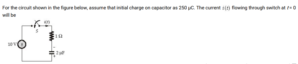
Transcribed Image Text:For the circuit shown in the figure below, assume that initial charge on capacitor as 250 µC. The current i(t) flowing through switch at t= 0
will be
12
10 V
2 µF
Expert Solution
This question has been solved!
Explore an expertly crafted, step-by-step solution for a thorough understanding of key concepts.

This is a popular solution!

Trending now
This is a popular solution!

Step by step
Solved in 3 steps with 2 images

Knowledge Booster


Learn more about
Need a deep-dive on the concept behind this application? Look no further. Learn more about this topic, electrical-engineering and related others by exploring similar questions and additional content below.Recommended textbooks for you
Delmar's Standard Textbook Of Electricity
Electrical Engineering
ISBN:
9781337900348
Author:
Stephen L. Herman
Publisher:
Cengage Learning
Delmar's Standard Textbook Of Electricity
Electrical Engineering
ISBN:
9781337900348
Author:
Stephen L. Herman
Publisher:
Cengage Learning