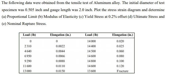
The following data were obtained from the tensile test of Aluminum alloy. The initial diameter of test specimen was 0.505 inch and gauge length was 2.0 inch. Plot the stress strain diagram and determine (a) Proportional Limit (b) Modulus of Elasticity (c) Yield Stress at 0.2% offset (d) Ultimate Stress and (e) Nominal Rupture Stress. Load (Ib) Elongation (in.) Load (Ib) Elongation (in.) 14 000 0.020 2310 0.0022 14400 0.025 4640 0.0044 14 500 0.060 6950 0.0066 14 600 0.080 9 290 0.0088 14 800 0.100 11 600 0.0110 14 600 0.120 13 000 0.0150 13 600 Fracture
The following data were obtained from the tensile test of Aluminum alloy. The initial diameter of test specimen was 0.505 inch and gauge length was 2.0 inch. Plot the stress strain diagram and determine (a) Proportional Limit (b) Modulus of Elasticity (c) Yield Stress at 0.2% offset (d) Ultimate Stress and (e) Nominal Rupture Stress. Load (Ib) Elongation (in.) Load (Ib) Elongation (in.) 14 000 0.020 2310 0.0022 14400 0.025 4640 0.0044 14 500 0.060 6950 0.0066 14 600 0.080 9 290 0.0088 14 800 0.100 11 600 0.0110 14 600 0.120 13 000 0.0150 13 600 Fracture

Steel Design (Activate Learning with these NEW titles from Engineering!)
6th Edition
ISBN:9781337094740
Author:Segui, William T.
Publisher:Segui, William T.
Chapter1: Introduction
Section: Chapter Questions
Problem 1.5.6P: The data in Table 1.5.3 were obtained from a tensile test of a metal specimen with a rectangular...

Related questions
Question
Transcribed Image Text:The following data were obtained from the tensile test of Aluminum alloy. The initial diameter of test
specimen was 0.505 inch and gauge length was 2.0 inch. Plot the stress strain diagram and determine
(a) Proportional Limit (b) Modulus of Elasticity (c) Yield Stress at 0.2% offset (d) Ultimate Stress and
(e) Nominal Rupture Stress.
Load (Ib)
Elongation (in.)
Load (Ib)
Elongation (in.)
14 000
0.020
2310
0.0022
14400
0.025
4640
0.0044
14 500
0.060
6950
0.0066
14 600
0.080
9 290
0.0088
14 800
0.100
11 600
0.0110
14 600
0.120
13 000
0.0150
13 600
Fracture
Expert Solution
This question has been solved!
Explore an expertly crafted, step-by-step solution for a thorough understanding of key concepts.

Step by step
Solved in 3 steps with 1 images

Recommended textbooks for you
Steel Design (Activate Learning with these NEW ti…
Civil Engineering
ISBN:
9781337094740
Author:
Segui, William T.
Publisher:
Cengage Learning

Materials Science And Engineering Properties
Civil Engineering
ISBN:
9781111988609
Author:
Charles Gilmore
Publisher:
Cengage Learning
Steel Design (Activate Learning with these NEW ti…
Civil Engineering
ISBN:
9781337094740
Author:
Segui, William T.
Publisher:
Cengage Learning
Materials Science And Engineering Properties
Civil Engineering
ISBN:
9781111988609
Author:
Charles Gilmore
Publisher:
Cengage Learning