(!) THE FOLLOWING QUESTIONS ARE BASED ON THE INFORMATION GIVEN HERE. R2 ww The emf source, E = 2.1 V, of the circuit shown in the figure has negligible internal resistance. The resistors have resistances R, = 2.6 N and R2 = 5.6 2. The capacitor has a capacitance C = 3.7 µF. R1 A) Determine the time constant T, in units of microseconds, for charging the capacitor. Answer: B) What is the charge Q on the capacitor in units of microcoulomb? Answer:
(!) THE FOLLOWING QUESTIONS ARE BASED ON THE INFORMATION GIVEN HERE. R2 ww The emf source, E = 2.1 V, of the circuit shown in the figure has negligible internal resistance. The resistors have resistances R, = 2.6 N and R2 = 5.6 2. The capacitor has a capacitance C = 3.7 µF. R1 A) Determine the time constant T, in units of microseconds, for charging the capacitor. Answer: B) What is the charge Q on the capacitor in units of microcoulomb? Answer:

Delmar's Standard Textbook Of Electricity
7th Edition
ISBN:9781337900348
Author:Stephen L. Herman
Publisher:Stephen L. Herman
Chapter20: Capacitance In Ac Circuits
Section: Chapter Questions
Problem 5PP: Three capacitors having capacitance values of 20F,40F, and 50F are connected in parallel to a 60 -...

Related questions
Question
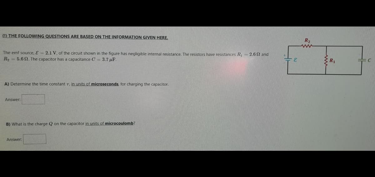
Transcribed Image Text:(!) THE FOLLOWING QUESTIONS ARE BASED ON THE INFORMATION GIVEN HERE,
R2
ww
The emf source, E = 2.1 V, of the circuit shown in the figure has negligible internal resistance. The resistors have resistances R, = 2.6 N and
R2 = 5.6 2. The capacitor has a capacitance C = 3.7 µF.
R1
A) Determine the time constant T, in units of microseconds, for charging the capacitor.
Answer:
B) What is the charge Q on the capacitor in units of microcoulomb?
Answer:
Expert Solution
This question has been solved!
Explore an expertly crafted, step-by-step solution for a thorough understanding of key concepts.

Step by step
Solved in 2 steps with 2 images

Knowledge Booster


Learn more about
Need a deep-dive on the concept behind this application? Look no further. Learn more about this topic, electrical-engineering and related others by exploring similar questions and additional content below.Recommended textbooks for you
Delmar's Standard Textbook Of Electricity
Electrical Engineering
ISBN:
9781337900348
Author:
Stephen L. Herman
Publisher:
Cengage Learning
Delmar's Standard Textbook Of Electricity
Electrical Engineering
ISBN:
9781337900348
Author:
Stephen L. Herman
Publisher:
Cengage Learning