The metal plate is held by two cables as shown in the following figure. If the force of each cable acting at A is FAB = 100 Ib and Fac = 200 Ib. Determine the magnitude of the resultant force of the two forces acting at A. -8 ft- 8 ft 6 ft B Y FAC FAR A(10;6;0) Select one: a. FR = 258.96 lb b. FR = 100 lb %3D c. FR = 200 Ib d. FR = 300 lb %3D
The metal plate is held by two cables as shown in the following figure. If the force of each cable acting at A is FAB = 100 Ib and Fac = 200 Ib. Determine the magnitude of the resultant force of the two forces acting at A. -8 ft- 8 ft 6 ft B Y FAC FAR A(10;6;0) Select one: a. FR = 258.96 lb b. FR = 100 lb %3D c. FR = 200 Ib d. FR = 300 lb %3D

Mechanics of Materials (MindTap Course List)
9th Edition
ISBN:9781337093347
Author:Barry J. Goodno, James M. Gere
Publisher:Barry J. Goodno, James M. Gere
Chapter2: Axially Loaded Members
Section: Chapter Questions
Problem 2.2.6P: By what distance h does the cage shown in the figure move downward when the weight W is placed...

Related questions

Question
Transcribed Image Text:* O l 42%016:05
R
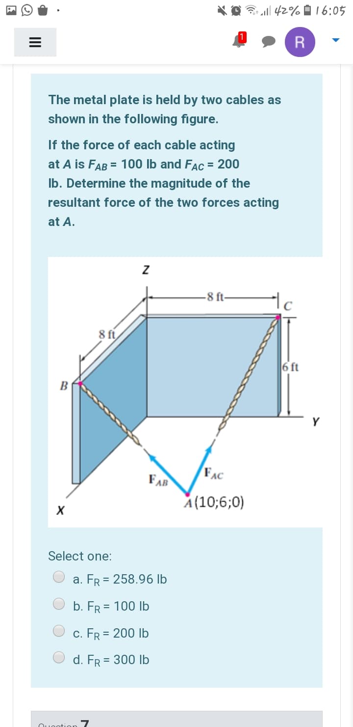
The metal plate is held by two cables as
shown in the following figure.
If the force of each cable acting
at A is FAB = 100 Ib and Fac = 200
Ib. Determine the magnitude of the
resultant force of the two forces acting
at A.
-8 ft-
8 ft
6 ft
B
Y
FAB
FAC
A(10;6;0)
Select one:
a. FR = 258.96 lb
b. FR = 100 Ib
c. FR = 200 Ib
d. FR = 300 Ib
Ouootion 7
II
Expert Solution
This question has been solved!
Explore an expertly crafted, step-by-step solution for a thorough understanding of key concepts.

Step by step
Solved in 2 steps with 2 images

Knowledge Booster


Learn more about
Need a deep-dive on the concept behind this application? Look no further. Learn more about this topic, mechanical-engineering and related others by exploring similar questions and additional content below.Recommended textbooks for you
Mechanics of Materials (MindTap Course List)
Mechanical Engineering
ISBN:
9781337093347
Author:
Barry J. Goodno, James M. Gere
Publisher:
Cengage Learning
Mechanics of Materials (MindTap Course List)
Mechanical Engineering
ISBN:
9781337093347
Author:
Barry J. Goodno, James M. Gere
Publisher:
Cengage Learning