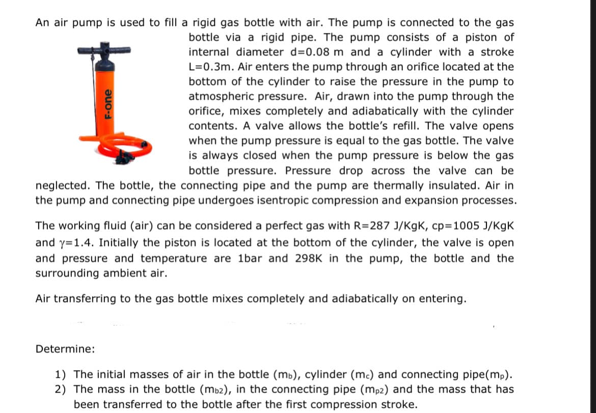
An air pump is used to fill a rigid gas bottle with air. The pump is connected to the gas bottle via a rigid pipe. The pump consists of a piston of internal diameter d=0.08 m and a cylinder with a stroke L=0.3m. Air enters the pump through an orifice located at the bottom of the cylinder to raise the pressure in the pump to atmospheric pressure Air drawn into the pump through the


Trending now
This is a popular solution!

Step by step
Solved in 5 steps with 7 images

The rest of the questions are thus:
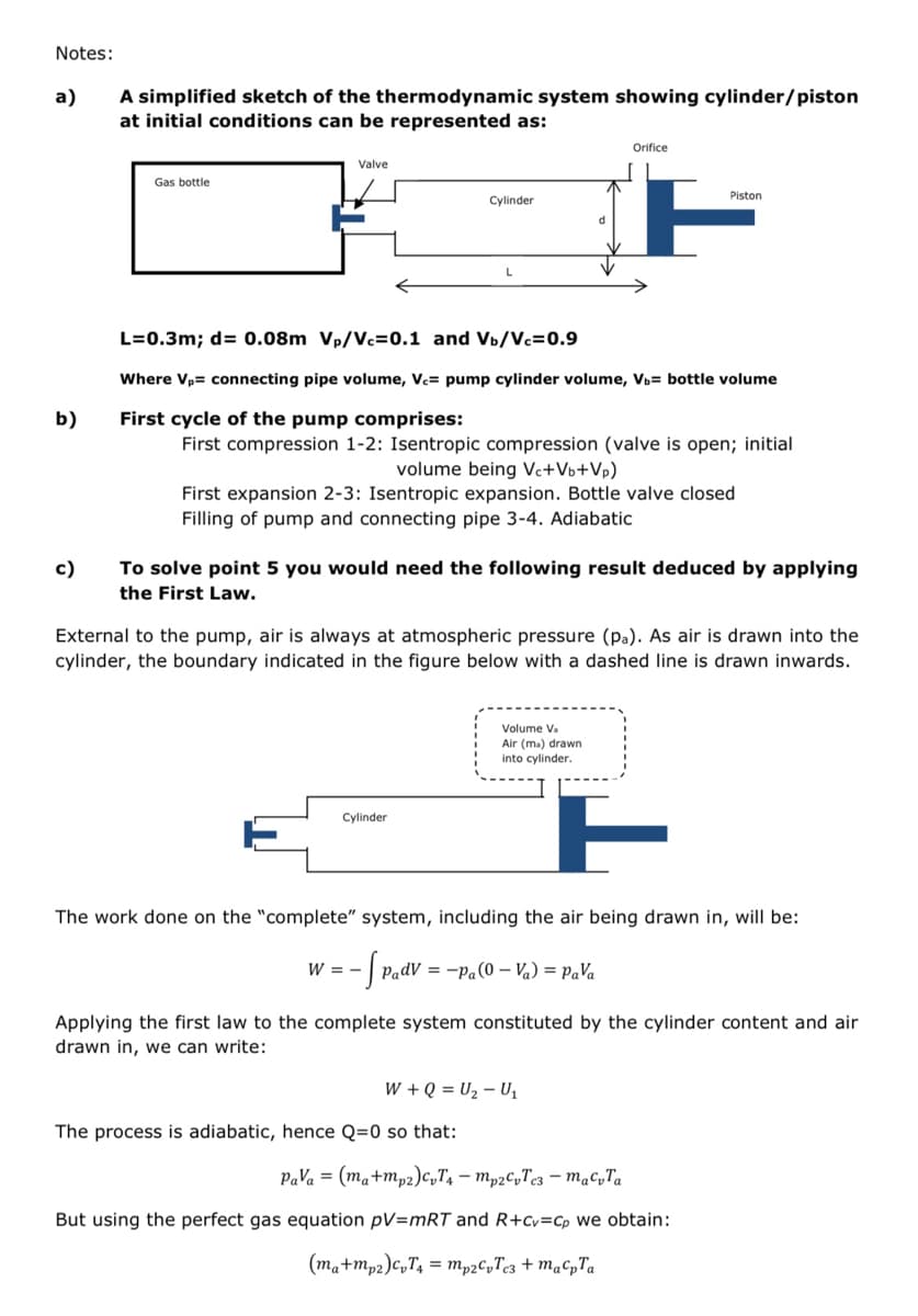
4) Calculate the air temperature and pressure in the pump at the end of the following expansion stroke, just before the piston uncovers the orifice (orifice dimensions are neglectable).
5) Calculate the mass and temperature of air in the pump (i.e. the cylinder and
connecting pipe) after the orifice has been exposed and the pressure has risen to atmospheric pressure (bottle valve is now closed).
7) Calculate the piston position and the air temperature in the pump during the next compression stroke at the time when the valve to the gas bottle opens again.
8) Calculate the pressure in the bottle when no more air can be transferred by the pump. (This will be after an undetermined number of pumping cycles).


