The shaft in Figure Q2.1 consists of three sections of different diameters and shear moduli as shown. It is fixed to a wall at A and loaded at points B.C and D. GAB 50 GPa AB= 60 mm 30 kNm 0.1 m Gac-70 GPa dac-80 mm 0.2 m Fig. Q2.1 GCD=50 GPa dcp = 40 mm с 20 kNm5 kNm 0.1 m D (a) Draw the Torque diagram for the shaft AD. Show all of your working and indicate all key values. (b) Determine the angle of twist for each section of the shaft (AB, BC and CD) and the total angle of twist between A and D. (c) If the shear strength for the entire shaft is 400 MPa, determine the maximum torque each section can withstand.
The shaft in Figure Q2.1 consists of three sections of different diameters and shear moduli as shown. It is fixed to a wall at A and loaded at points B.C and D. GAB 50 GPa AB= 60 mm 30 kNm 0.1 m Gac-70 GPa dac-80 mm 0.2 m Fig. Q2.1 GCD=50 GPa dcp = 40 mm с 20 kNm5 kNm 0.1 m D (a) Draw the Torque diagram for the shaft AD. Show all of your working and indicate all key values. (b) Determine the angle of twist for each section of the shaft (AB, BC and CD) and the total angle of twist between A and D. (c) If the shear strength for the entire shaft is 400 MPa, determine the maximum torque each section can withstand.

Mechanics of Materials (MindTap Course List)
9th Edition
ISBN:9781337093347
Author:Barry J. Goodno, James M. Gere
Publisher:Barry J. Goodno, James M. Gere
Chapter3: Torsion
Section: Chapter Questions
Problem 3.3.12P: A propeller shaft for a small yacht is made of a solid steel bar 104 mm in diameter. The allowable...

Related questions

Question
Transcribed Image Text:Q2
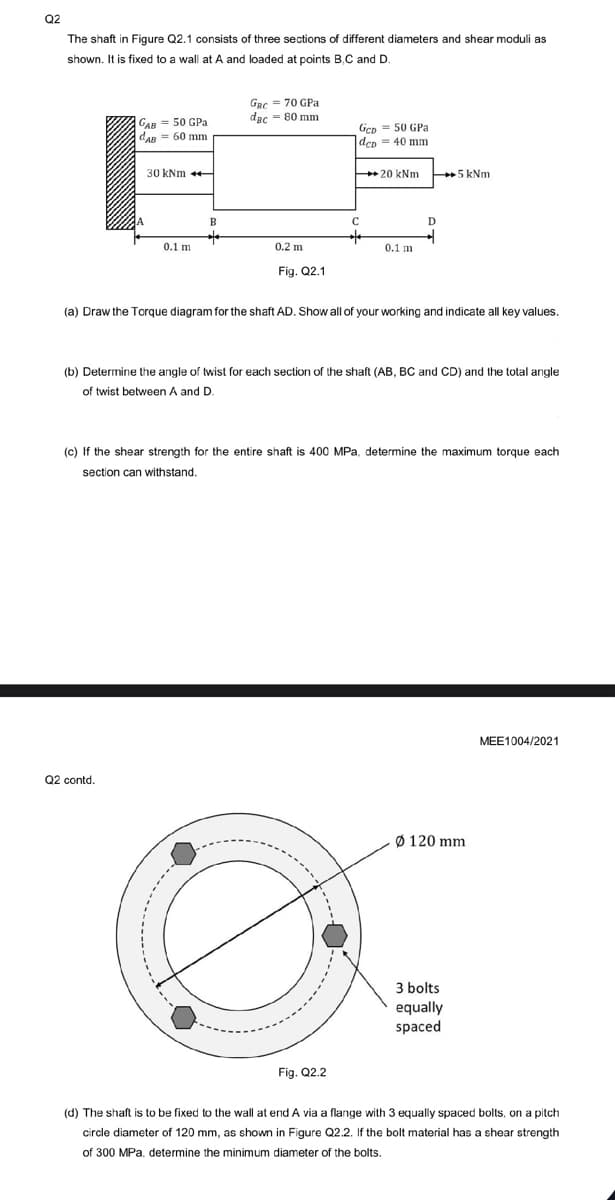
The shaft in Figure Q2.1 consists of three sections of different diameters and shear moduli as
shown. It is fixed to a wall at A and loaded at points B.C and D.
GAB 50 GPa
dAB = 60 mm
30 kNm ++
0.1 m
Q2 contd.
B
**
GRC = 70 GPa
dac = 80 mm
0.2 m
Fig. Q2.1
Gcp= 50 GPa
dep 40 mm
C
20 kNm
Fig. Q2.2
0.1 m
D
(a) Draw the Torque diagram for the shaft AD. Show all of your working and indicate all key values.
(b) Determine the angle of twist for each section of the shaft (AB, BC and CD) and the total angle
of twist between A and D.
5 kNm
(c) If the shear strength for the entire shaft is 400 MPa, determine the maximum torque each
section can withstand.
Ø 120 mm
3 bolts
equally
spaced
MEE1004/2021
(d) The shaft is to be fixed to the wall at end A via a flange with 3 equally spaced bolts, on a pitch
circle diameter of 120 mm, as shown in Figure Q2.2. If the bolt material has a shear strength
of 300 MPa, determine the minimum diameter of the bolts.
Expert Solution
This question has been solved!
Explore an expertly crafted, step-by-step solution for a thorough understanding of key concepts.

Step by step
Solved in 3 steps with 1 images

Knowledge Booster


Learn more about
Need a deep-dive on the concept behind this application? Look no further. Learn more about this topic, mechanical-engineering and related others by exploring similar questions and additional content below.Recommended textbooks for you
Mechanics of Materials (MindTap Course List)
Mechanical Engineering
ISBN:
9781337093347
Author:
Barry J. Goodno, James M. Gere
Publisher:
Cengage Learning
Mechanics of Materials (MindTap Course List)
Mechanical Engineering
ISBN:
9781337093347
Author:
Barry J. Goodno, James M. Gere
Publisher:
Cengage Learning