The switch opens after having been closed a long time. Find the inductor current, inductor voltage, capacitor current and capacitor voltage at the following three times: t = 0-, t = 0+, t->infinity i: 2 mH + V: ic 20 kN =0 10 mA 30kN Ve 6 µF
Q: Example-4: 2 H 3 H ll 5 V 6 A 2 F
A:
Q: 6.41.1 The voltage across an inductor with 2 H capacitance is 12. (1 – e-dr) v, where a = 1.2. If…
A: Inductor doesn't allow Sudden change of current.
Q: 5. Determine the time constant, in seconds, for an inductor coil with an inductance of 0.5 H and…
A: TIME CONSTANT:- It is the time required to reach the response to 63.2% of of final value while…
Q: 0.5 H 312.5 µF 4V R= 16 1, L =0,5 H, C = 312, 5 µF Vs(t)=4 V Vc(t)-V(t) Constant voltage source…
A:
Q: H1) For the circuit of Figure below, compute the energy stored in the 10 mH inductor at t = 100 ms.…
A: The 5u0(t) source will be active only for t>0 and thus it will be equal to 5A. We will do source…
Q: In an RC series circuit, E= 12.0 V, R = 1.40 M2, and C =1.80 uF. (a) Calculate the time constant.…
A: This question belongs to circuit theory . It is based on the concept of charge developed in series…
Q: n 21 Consider the circuit shown with &= 50 V, R=250 0, L=281 mH, and C=0.5 µF. The open switch is…
A:
Q: Solve for the value of v and i at any time t when the switch is closed in position 1 for a…
A:
Q: A 400V, 50HZ star connected induction motor takes a line current of 50 Amps At a p.f. of 0.8…
A: Given, A star connected induction motor VL=400 Vf=50 HzIL=50 Apf1=cosϕ1=0.8 laggingpf2=cosϕ2=0.9
Q: H.W.: A voltage source, vs = 20u(t) V, is in series with a 200 Q resistor and a 4 H inductor. Find…
A:
Q: The current I(t) through a 5.0-mH inductor varies with time, as shown below. The resistance of the…
A: Graph between time and current is given as, From the graph at t = 2 ms current is equal to 4 A.
Q: Question 10 A pure inductance of 100mH is connected in parallel to a 25μF capacitor. The network is…
A:
Q: A 5-H inductor changes its current by 3 A in 0.2 s, the voltage produced at the :terminals of the…
A: Inductor(L)=5H Change in current (dI)=3A Change in time(dt)=0.2sec
Q: 3. If the switch changes position (from a-b to b-c) at t=0, find the inductor current it(t) for t>0.…
A: For t<0, The circuit is, Since the circuit has been in this position for a long time the…
Q: t=0 IL 1H 20 2 20 2 48 V ll
A: Given circuit shown
Q: If two identical inductors are magnetically coupled, the mutual inductance is 10 mH and the…
A: Given two identical inductors are magnetically coupled, Let the inductance of both the inductors,…
Q: The circuit shown below has been connected for a long time. What is the energy stored in the 5 H…
A: At steady state inductor short circuited and capacitor open circuited. We will apply nodal analysis…
Q: Exercise#6: The current through a 250-mH inductor takes the following values. Calculate he…
A: The relation between the voltage and current is as follows for the inductor V = L di/dt L = inductor…
Q: The inductor in the figure (Figure 1) has inductance 0.260 H and carries a current in the direction…
A: Given: Inductor having inductance, L = 0.260 H Current decreasing at uniform rate, didt=-1.80×10⁻²…
Q: The switch in the following circuit has been closed for a long time. At t = Os it opens…
A:
Q: A 40µF capacitor in series with a coil of resistance 8 ohms and inductance 80mH is connected to a…
A:
Q: The circuit below contains two light bulbs, a capacitor, and an inductor. At the instant shown, (1)…
A: Given E=3 VR1=150 ΩR2=250 ΩC=200 μFL=500 mH (a) The potential differences across bulb 1 and…
Q: Consider a 20 µF capacitor charged to 45 V. The charged capacitor is then connected to a 3.0 mH…
A: Given C= 20uF L= 3mH V= 45V
Q: Determine the value of the intial and final energy of the 3 H inductor whose current for t> 0 is…
A:
Q: Problem 1 The switch in the following circuit has been closed for a long time. At t = Os the switch…
A:
Q: What is the inductor current at t= 200 µs the circuit shown? 50 mH 1 k2 X t=0 5 mA, 2502 İL = _ mA
A: The given circuit is
Q: 5 A/sec and -8 V/sec
A:
Q: A parallel-plate capacitor has plates measuring 10 cm x 10 cm, spaced 1 mm apart. The dielectric is…
A:
Q: Imagine a current carrying coil with a length of 1.847 cm and a cross-sectional area of 1.96 cm…
A:
Q: When the switch is in position A, the capacitor C, is fully charged while the capacitors C2 and C3…
A:
Q: 03: The switch in the circuit shown has beeln TII position 1 for a long timc. At t = 0 it moves…
A:
Q: 11. A parallel plate capacitor has the following values k=81, d=0.025 inches, A= 6 square inches.…
A:
Q: Problem #1: If the current flowing through a 75mH inductor has the waveform shown below, (a)…
A: Using slope equation calculate expression for inductor current. Voltage across inductor = Ldi/dt.
Q: 8. A 4.7M ohms resistor is in series with a 0.15 farad capacitor. The combination is across a 12 V…
A:
Q: t = 0 14 0 1/8 H 12 0 Figure 1
A:
Q: A fixed current of 100 mA passes an inductor of 20 mH. How much energy is stored in this inductor in…
A: Given: Fixed current passed through inductor, I=100 mA Inductance, L=20 mH
Q: If a constant current of 440 µA charges a capacitor of value 2.2 mF, with an initial voltage of 1.25…
A: Current through the capacitor = C dv/dt Where C is capacitance Using above formula calculate…
Q: 1. A 10 μF capacitor is connected in series with a 5 Ω resistor and a battery of negligible internal…
A: Resistors, inductors and capacitors form an integral part of any electrical circuit. A source,…
Q: a) How long will it take the capacitor to discharge to 25 v after the switch is closed C 100 V R 2.2…
A: In this question, We need to determine the time to take to reach 25V across the capacitor? And in…
Q: 5. In a circuit, the capacitors are all initially uncharged and the switch S is originally open.…
A: This is a question of network analysis. It is related to transient analysis with 2 energy elements…
Q: The circuit in the figure below has been connected for a long time. Let R, = 8.80 Q and R, = 3.80 Q.…
A:
Q: A 100 μf condenser has a charge of 0.02 coulomb. If it is discharged through a 500 Ω resistor, what…
A: The capacitor discharging equation is given below; Q(t)= charge in capacitor at time t. Qo =…
Q: When the supply current is minimum find the capacitance of a coil of inductance one hundred…
A:
Q: How should 4 capacitors, C1 = 2 µF, C2 = 4 µF, C3 = 6 µF and C4 = 8 µF be connected to have a…
A:
Q: QUESTION 3 Consider the shown circuit, with the capacitor initially uncharged. When the switch S is…
A: Find the time t it take the capacitor to be charged by 25% of it's final maximum charge if the…
Q: A 752 uF capacitor has an initial voltage, v(0) = 1 V. If the current flowing through the capacitor…
A: In the above question the the voltage at t=0 is 1V the voltage at time =t can be found using the…
Q: For your final exam in electronics, you're asked to build an LC circuit that oscillates at 11 kHz.…
A:
Q: Write a small essay about discharging capacitor then: For the circuit shown, the switch was open for…
A:
Subject: Fundamentals of engineering.
Please show all works
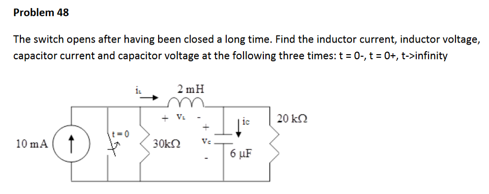
Trending now
This is a popular solution!
Step by step
Solved in 3 steps with 3 images
- Three capacitors having capacitance values of 20F,40F, and 50F are connected in parallel to a 60 - Hz power line. An ammeter indicates a circuit current of 8.6 amperes. How much current is flowing through the 40F capacitor?You are working in an industrial plant. You have been instructed to double the capacitance connected to a machine. The markings on the capacitor, however, are not visible. The capacitor is connected to 560 volts and an ammeter indicates a current of 6 amperes flowing to the capacitor. What size capacitor should be connected in parallel with the existing capacitor? What is the minimum AC voltage rating of the new capacitor? What is the minimum DC voltage rating of the new capacitor? What is the minimum KVAR size that can be used in this installation?You are an electrician working in an industrial plant. You discover that the problem with a certain machine is a defective capacitor. The capacitor is connected to a 240-volt AC circuit. The information on the capacitor reveals that it has a capacitance value of 10 mF and a voltage rating of 240 VAC. The only 10-mF AC capacitor in the storeroom is marked with a voltage rating of 350 WVDC. Can this capacitor be used to replace the defective capacitor? Explain your answer.
- Inductive Circuits Fill in all the missing values. Refer to the following formulas: XL=2fLL=XL2ff=XL2L Inductance (H) Frequency (Hz) Inductive Reactance ( ) 1.2 60 0.085 213.628 1000 4712.389 0.65 600 3.6 678.584 25 411.459 0.5 60 0.85 6408.849 20 201.062 0.45 400 4.8 2412.743 1000 40.841A capacitor uses air as a dielectric and has a capacitance of 3 F. A dielectric material is inserted between the plates without changing the spacing, and the capacitance becomes 15 F. What is the dielectric constant of this material?You are a journeyman electrician working in an industrial plant. Your task is to connect an inductor to a 480-V, 60-Hz line. To determine the proper conductor and fuse size for this installation, you need to know the amount of current the inductor will draw from the line. The nameplate on the inductor indicates that it has an inductance of 0.1 H. An ohmmeter reveals that it has a wire resistance of 10 . How much current should this inductor draw when connected to the line?
- A postage stamp mica capacitor has the following color marks starting at the upper left dot: yellow, violet, brown, green, no color, and blue. What are the capacitance value, tolerance, and voltage rating of this capacitor?You find that a 25-F capacitor connected to 480 VAC is defective. The storeroom has no capacitors with a 480-VAC rating. However, you find two capacitors rated at 50 F and 370 VAC. Can these two capacitors be connected in such a manner that they can replace the defective capacitor? If yes, explain how they are connected and why the capacitors will not be damaged by the lower voltage rating. If no, explain why they cannot be used without damaging the capacitor.Describe the behavior of the following circuit under the following scenario: (1) Begin with switch S1 open, (2) close switch S1 long enough till the voltage across the inductor is almost zero, and then (3) open switch S1 for a long time beginning at time t = 0.
- Design a single circuit element containing one inductor, one capacitor and one resistor with v(t)=-3e-3tV and i(t)=4+2e-3tA for t>0. Also specify the value of the inductance, capacitance and the resistance of the three element.An RC circuit (see Figure 4) contains a resistor (10 ohms) anda capacitor (0.2 F) linked in series with an electromotiveforce E(t) = 10 sin 2πt.(a) Use a numerical solver to sketch the graph of thecharge on the capacitor versus time for each of theinitial conditions Q(0) = −1, −0.75, −0.5,..., 1 onthe time interval [0, 15]. What appears to happen toeach of the solutions with the passage of time? Explain what might be meant by a steady-state response.(b) What is the frequency of the emf? What appears to bethe frequency of the steady-state response? Hint: Recall that in the function f (t) = sin ωt, ω is called theangular frequency, the period is given by T = 2π/ω,and the frequency is the reciprocal of the period.Think of the frequency as the number of cycles persecond, a unit known as Hertz (Hz).All capacitors were initially discharged. at t = 0, S1 is placed at position 1 and S2 is closed. Calculate the Thevenin-equivalent voltage seen by the equivalent capacitor during this phase. Enter your answer in V rounded to 2 decimal places. At t = 15 ms, S1 is placed at position 2 and S2 is kept closed. At t = 25 ms, S1 is kept at position 2 and S2 is opened. Data: V1 = 20 V; R1 = 8.0 kΩ, R2 = 10 kΩ, R3 = 2.5 kΩ, R4 = 3 kΩ, R5 = 16 kΩ, R6 = 10.5 kΩ; C1 = 3.5 µF, C2 = 7.0 µF, C3 = 13 µF