This question does NOT need to be solved, but I would appreciate some clarification. -------- PROBLEM: Collar A has a ramp that is welded to it and a force P = 5 lb applied as shown. Collar A and the ramp weigh 3 lb, and block B weighs 0.8 lb. Neglecting friction, determine the tension in the cable. ------- Can you explain in detail how to do the constraint equations ( in general)? And then specifically explain in this case why it is XB/A and how the two tension from the cable with block B does not effect the equation (figure four)? I understand how to solve it but I am still having trouble with the constraint equations.
This question does NOT need to be solved, but I would appreciate some clarification. -------- PROBLEM: Collar A has a ramp that is welded to it and a force P = 5 lb applied as shown. Collar A and the ramp weigh 3 lb, and block B weighs 0.8 lb. Neglecting friction, determine the tension in the cable. ------- Can you explain in detail how to do the constraint equations ( in general)? And then specifically explain in this case why it is XB/A and how the two tension from the cable with block B does not effect the equation (figure four)? I understand how to solve it but I am still having trouble with the constraint equations.

International Edition---engineering Mechanics: Statics, 4th Edition
4th Edition
ISBN:9781305501607
Author:Andrew Pytel And Jaan Kiusalaas
Publisher:Andrew Pytel And Jaan Kiusalaas
Chapter5: Three-dimensional Equilibrium
Section: Chapter Questions
Problem 5.13P: In Sample Problem 5.4, determine the tension TAC using the equation MDB=0.

Related questions

Question
This question does NOT need to be solved, but I would appreciate some clarification.
--------
PROBLEM: Collar A has a ramp that is welded to it and a force P = 5 lb applied as shown. Collar A and the ramp weigh 3 lb, and block B weighs 0.8 lb. Neglecting friction, determine the tension in the cable.
-------
Can you explain in detail how to do the constraint equations ( in general)? And then specifically explain in this case why it is XB/A and how the two tension from the cable with block B does not effect the equation (figure four)? I understand how to solve it but I am still having trouble with the constraint equations.
Transcribed Image Text:XA
W
0 = 50°
XB/A
B
Fig. 4.
Position vectors for
dependent motion.
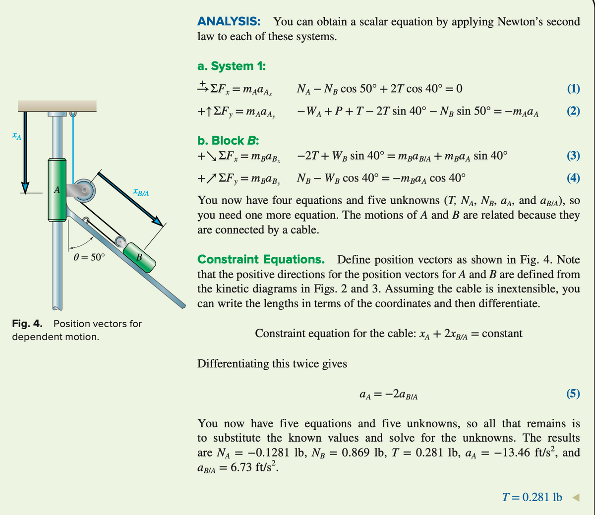
ANALYSIS: You can obtain a scalar equation by applying Newton's second
law to each of these systems.
a. System 1:
ΕΣΕ. =mдaАx
+1EF, = mAday
b. Block B:
+\ ΣFx = mBª Bx
NA - NB COS 50° +27 cos 40° = 0
-WA+P+T-27 sin 40° - NB sin 50° = -mдад
−2T+ Wg sin 40° = mpa BIA + mua, sin 40°
(3)
+/ΣF₂= m BaBy
NB - WB cos 40° = −mª cos 40°
(4)
You now have four equations and five unknowns (T, NÃ, Nâ, ªд, and aBIA), so
you need one more equation. The motions of A and B are related because they
are connected by a cable.
(1)
(2)
Constraint Equations. Define position vectors as shown in Fig. 4. Note
that the positive directions for the position vectors for A and B are defined from
the kinetic diagrams in Figs. 2 and 3. Assuming the cable is inextensible, you
can write the lengths in terms of the coordinates and then differentiate.
Constraint equation for the cable: XA + 2XB/A = constant
Differentiating this twice gives
aε = -2a BIA
(5)
You now have five equations and five unknowns, so all that remains is
to substitute the known values and solve for the unknowns. The results
are N₁ = -0.1281 lb, NB 0.869 lb, T = 0.281 lb, a = −13.46 ft/s², and
aBIA = 6.73 ft/s².
=
T= 0.281 lb
Transcribed Image Text:P
A
W
0 = 50°
0 = 50°
B
System 1
B
-System 2
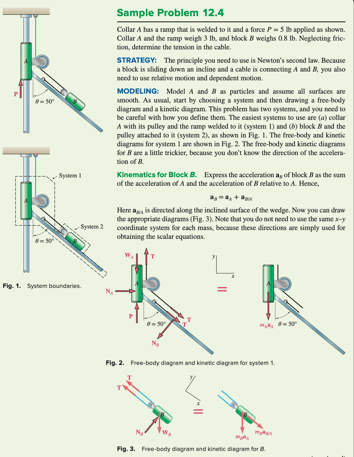
Fig. 1. System boundaries.
Sample Problem 12.4
Collar A has a ramp that is welded to it and a force P = 5 lb applied as shown.
Collar A and the ramp weigh 3 lb, and block B weighs 0.8 lb. Neglecting fric-
tion, determine the tension in the cable.
STRATEGY: The principle you need to use is Newton's second law. Because
a block is sliding down an incline and a cable is connecting A and B, you also
need to use relative motion and dependent motion.
MODELING: Model A and B as particles and assume all surfaces are
smooth. As usual, start by choosing a system and then drawing a free-body
diagram and a kinetic diagram. This problem has two systems, and you need to
be careful with how you define them. The easiest systems to use are (a) collar
A with its pulley and the ramp welded to it (system 1) and (b) block B and the
pulley attached to it (system 2), as shown in Fig. 1. The free-body and kinetic
diagrams for system 1 are shown in Fig. 2. The free-body and kinetic diagrams
for B are a little trickier, because you don't know the direction of the accelera-
tion of B.
Kinematics for Block B. Express the acceleration as of block B as the sum
of the acceleration of A and the acceleration of B relative to A. Hence,
aB=aA + aBIA
Here
aBIA
is directed along the inclined surface of the wedge. Now you can draw
the appropriate diagrams (Fig. 3). Note that you do not need to use the same x-y
coordinate system for each mass, because these directions are simply used for
obtaining the scalar equations.
W
T
T
T
0 = 50°
NB
T
Fig. 2. Free-body diagram and kinetic diagram for system 1.
B
y
L
X
mдªA
mBªB/A
mBa A
Fig. 3. Free-body diagram and kinetic diagram for B.
0 = 50°
Expert Solution
This question has been solved!
Explore an expertly crafted, step-by-step solution for a thorough understanding of key concepts.

This is a popular solution!

Trending now
This is a popular solution!

Step by step
Solved in 4 steps with 4 images

Knowledge Booster


Learn more about
Need a deep-dive on the concept behind this application? Look no further. Learn more about this topic, mechanical-engineering and related others by exploring similar questions and additional content below.Recommended textbooks for you
International Edition---engineering Mechanics: St…
Mechanical Engineering
ISBN:
9781305501607
Author:
Andrew Pytel And Jaan Kiusalaas
Publisher:
CENGAGE L
International Edition---engineering Mechanics: St…
Mechanical Engineering
ISBN:
9781305501607
Author:
Andrew Pytel And Jaan Kiusalaas
Publisher:
CENGAGE L