· Three forces are applied to the structure shown in Figure 3. Determine the maximum possible normal and shear stresses at point A under these combined loadings. 50 mm 20 mm A 40 mm 2.5 KN 150 mm 0.5 kN 160 mm 3 kN
· Three forces are applied to the structure shown in Figure 3. Determine the maximum possible normal and shear stresses at point A under these combined loadings. 50 mm 20 mm A 40 mm 2.5 KN 150 mm 0.5 kN 160 mm 3 kN

Mechanics of Materials (MindTap Course List)
9th Edition
ISBN:9781337093347
Author:Barry J. Goodno, James M. Gere
Publisher:Barry J. Goodno, James M. Gere
Chapter7: Analysis Of Stress And Strain
Section: Chapter Questions
Problem 7.3.7P: The normal and shear stresses acting on element A are 6500 psi, 17,300 psi, and 2900 psi (see the...

Related questions

Question
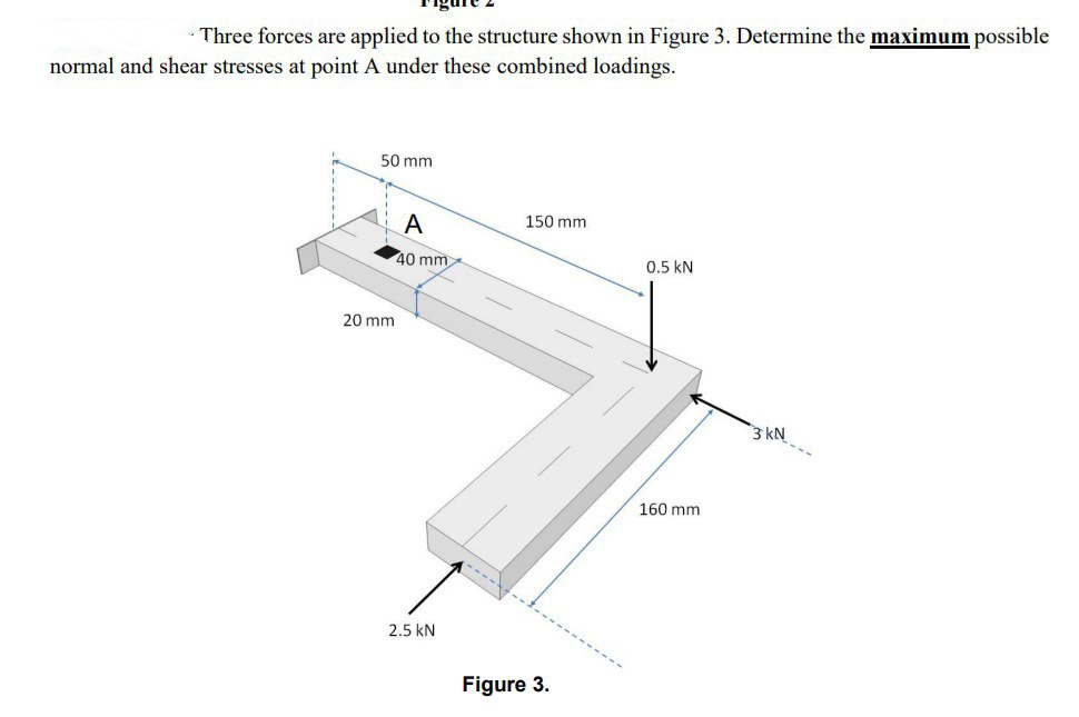
Transcribed Image Text:Three forces are applied to the structure shown in Figure 3. Determine the maximum possible
normal and shear stresses at point A under these combined loadings.
50 mm
20 mm
A
40 mm
2.5 KN
150 mm
Figure 3.
0.5 kN
160 mm
3 kN
Expert Solution
This question has been solved!
Explore an expertly crafted, step-by-step solution for a thorough understanding of key concepts.

Step by step
Solved in 4 steps with 1 images

Knowledge Booster


Learn more about
Need a deep-dive on the concept behind this application? Look no further. Learn more about this topic, mechanical-engineering and related others by exploring similar questions and additional content below.Recommended textbooks for you
Mechanics of Materials (MindTap Course List)
Mechanical Engineering
ISBN:
9781337093347
Author:
Barry J. Goodno, James M. Gere
Publisher:
Cengage Learning
Mechanics of Materials (MindTap Course List)
Mechanical Engineering
ISBN:
9781337093347
Author:
Barry J. Goodno, James M. Gere
Publisher:
Cengage Learning