To reduce the switching harmonics present in the input current of a certain buck converter, an input filter is added as shown in Fig. 3.33. Inductors L, and L, contain winding resistances R₁ and R2, respec- tively. The MOSFET has on-resistance R and the diode forward voltage drop can be modeled by a constant voltage V, plus a resistor R. All other losses can be ignored. 4 m (a) (b) (c) Ru w C₁ Q₁ T D, T Fig. 3.33 Buck converter with input filter, Problem 3.6. 4 R₁2 mom C₂ Derive a complete equivalent circuit model for this circuit. Solve your model to find the de output voltage V. Derive an expression for the efficiency. Manipulate your expression into a form similar to Eq. (3.35)
To reduce the switching harmonics present in the input current of a certain buck converter, an input filter is added as shown in Fig. 3.33. Inductors L, and L, contain winding resistances R₁ and R2, respec- tively. The MOSFET has on-resistance R and the diode forward voltage drop can be modeled by a constant voltage V, plus a resistor R. All other losses can be ignored. 4 m (a) (b) (c) Ru w C₁ Q₁ T D, T Fig. 3.33 Buck converter with input filter, Problem 3.6. 4 R₁2 mom C₂ Derive a complete equivalent circuit model for this circuit. Solve your model to find the de output voltage V. Derive an expression for the efficiency. Manipulate your expression into a form similar to Eq. (3.35)

Introductory Circuit Analysis (13th Edition)
13th Edition
ISBN:9780133923605
Author:Robert L. Boylestad
Publisher:Robert L. Boylestad
Chapter1: Introduction
Section: Chapter Questions
Problem 1P: Visit your local library (at school or home) and describe the extent to which it provides literature...

Related questions

Question
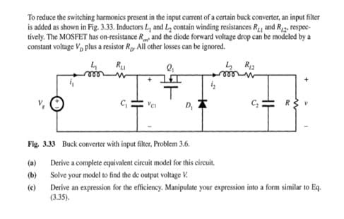
Transcribed Image Text:To reduce the switching harmonics present in the input current of a certain buck converter, an input filter
is added as shown in Fig. 3.33. Inductors L, and L₂ contain winding resistances R₁₁ and R2, respec-
tively. The MOSFET has on-resistance Rand the diode forward voltage drop can be modeled by a
constant voltage V plus a resistor Rp. All other losses can be ignored.
Ru
4 R₁2
C₁
(a)
(b)
(c)
2₁
+I
T
D,
Fig. 3.33 Buck converter with input filter, Problem 3.6.
Derive a complete equivalent circuit model for this circuit.
Solve your model to find the de output voltage V.
C₂: R
Derive an expression for the efficiency. Manipulate your expression into a form similar to Eq.
(3.35).
Expert Solution
This question has been solved!
Explore an expertly crafted, step-by-step solution for a thorough understanding of key concepts.

Step by step
Solved in 4 steps with 4 images

Knowledge Booster


Learn more about
Need a deep-dive on the concept behind this application? Look no further. Learn more about this topic, electrical-engineering and related others by exploring similar questions and additional content below.Recommended textbooks for you
Introductory Circuit Analysis (13th Edition)
Electrical Engineering
ISBN:
9780133923605
Author:
Robert L. Boylestad
Publisher:
PEARSON

Delmar's Standard Textbook Of Electricity
Electrical Engineering
ISBN:
9781337900348
Author:
Stephen L. Herman
Publisher:
Cengage Learning

Programmable Logic Controllers
Electrical Engineering
ISBN:
9780073373843
Author:
Frank D. Petruzella
Publisher:
McGraw-Hill Education
Introductory Circuit Analysis (13th Edition)
Electrical Engineering
ISBN:
9780133923605
Author:
Robert L. Boylestad
Publisher:
PEARSON
Delmar's Standard Textbook Of Electricity
Electrical Engineering
ISBN:
9781337900348
Author:
Stephen L. Herman
Publisher:
Cengage Learning
Programmable Logic Controllers
Electrical Engineering
ISBN:
9780073373843
Author:
Frank D. Petruzella
Publisher:
McGraw-Hill Education

Fundamentals of Electric Circuits
Electrical Engineering
ISBN:
9780078028229
Author:
Charles K Alexander, Matthew Sadiku
Publisher:
McGraw-Hill Education

Electric Circuits. (11th Edition)
Electrical Engineering
ISBN:
9780134746968
Author:
James W. Nilsson, Susan Riedel
Publisher:
PEARSON

Engineering Electromagnetics
Electrical Engineering
ISBN:
9780078028151
Author:
Hayt, William H. (william Hart), Jr, BUCK, John A.
Publisher:
Mcgraw-hill Education,