Two alternating voltages are represented by v1=50sinwt volts and v2=100sin (wt – 1/6) V. Find the sinusoidal expression to represent v1 + v2. 145.5sin (wt - 0.35) V 145.5sin (wt + 0.35) V 154.5sin (wt + 0.35) V 154.5sin (wt + 0.35) V
Two alternating voltages are represented by v1=50sinwt volts and v2=100sin (wt – 1/6) V. Find the sinusoidal expression to represent v1 + v2. 145.5sin (wt - 0.35) V 145.5sin (wt + 0.35) V 154.5sin (wt + 0.35) V 154.5sin (wt + 0.35) V

Power System Analysis and Design (MindTap Course List)
6th Edition
ISBN:9781305632134
Author:J. Duncan Glover, Thomas Overbye, Mulukutla S. Sarma
Publisher:J. Duncan Glover, Thomas Overbye, Mulukutla S. Sarma
Chapter6: Power Flows
Section: Chapter Questions
Problem 6.61P

Related questions
Question
Kindly provide a CLEAR and COMPLETE solution.
#11
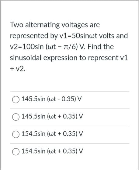
Transcribed Image Text:Two alternating voltages are
represented by v1=50sinwt volts and
v2=100sin (wt - 1/6) V. Find the
sinusoidal expression to represent v1
+ v2.
145.5sin (wt - 0.35) V
145.5sin (wt + 0.35) V
154.5sin (wt + 0.35) V
154.5sin (wt + 0.35) V
Expert Solution
This question has been solved!
Explore an expertly crafted, step-by-step solution for a thorough understanding of key concepts.

Step by step
Solved in 2 steps with 2 images

Knowledge Booster


Learn more about
Need a deep-dive on the concept behind this application? Look no further. Learn more about this topic, electrical-engineering and related others by exploring similar questions and additional content below.Recommended textbooks for you
Power System Analysis and Design (MindTap Course …
Electrical Engineering
ISBN:
9781305632134
Author:
J. Duncan Glover, Thomas Overbye, Mulukutla S. Sarma
Publisher:
Cengage Learning
Power System Analysis and Design (MindTap Course …
Electrical Engineering
ISBN:
9781305632134
Author:
J. Duncan Glover, Thomas Overbye, Mulukutla S. Sarma
Publisher:
Cengage Learning