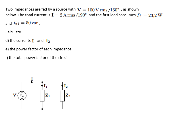
Two impedances are fed by a source with V = 100 V rms /160° , as shown below. The total current is I = 2 A rms /190° and the first load consumes P = 23,2 W and Q1 = 50 var. Calculate d) the currents I, and I2 e) the power factor of each impedance f) the total power factor of the circuit
Q: Three loads are connected in parallel across a 250 V(rms) line, asshown . Load 1 absorbs 16 kW and…
A: Load 1 absorbs active power of 16 KW and reactive power of 18 KVAR. Therefore, Apparent power is…
Q: A 250 V rms system is supplying three parallel loads. One draw 20kW at unity pf, a second uses 25…
A: The complex power in an AC system is defined as the product of rms value of applied voltage and…
Q: The variable load resistor RL in the circuit shown is adjusted for maximum average power transfer to…
A: Applying Thevenin’s theorem , for calculating Thevenin’s voltage by removing load resistance…
Q: AC chopper circuit shown in the figure, the thyristor T1 is triggered at an angle a (180 <a <360). V…
A: For the given AC chopper circuit, the input voltage is vint=100sinωt V. The thyristor T1 is fired…
Q: Q1b. Write the phasor form of v(t)= 12 sin (200t+30°) V Q1c. You have a load that has an impedance…
A: For this problem we can easily solve .
Q: Q.19: For the circuit shown: 1. Find the phasor currents i, & i2? 2. Compute the total power. JIQ…
A:
Q: For the circuit show below, solve for the following: a. The complex power delivered to each passive…
A:
Q: Given the following Thevenin equivalent circuit. We connected a load ZL and its value is chosen to…
A: The correct option is given below
Q: For the diagram below calculate the Total Real Power (PT),; The Total Reactive Power (QT); the Total…
A:
Q: Be able to calculate all forms of ac power in ac circuits with linear transformers and ideal…
A:
Q: RLine jXLine LV(rms) Three loads are supplied through a line in the figure. Calculate the efficiency…
A: An a.c circuit differs from a d.c circuit in many respects. First, in a d.c circuit we consider…
Q: 4. A 250 V rms system is supplying three parallel loads. One draw 20kW at unity pf, a second uses 25…
A: The circuit has real power, reactive power and the apparent power. The angle of apparent power is…
Q: Part A - Power and power factor for parallel loads I Consider the two loads in the circuit in…
A: Part (a) Fig: Circuit diagram Given that, S1=100KVA S2=70KVA pf1=cosϕ1=0.75 (leading)…
Q: As shown in Figure Q1(b), two loads A and B are connected in parallel across a 1.5 kV r 60-Hz line.…
A: The solution can be achieved as follows.
Q: The three loads in the circuit can be described as follows: Load 1 is a…
A: Load 1 The connected resistance is 240 Ω resistor in series with an inductive reactance of 70 Ω.…
Q: The RMS voltage and RMS current associated with the black box below are: V(t) = 0.8 COS (1200t+85)…
A: Given: V(t) = 0.8 cos (1200t+85) V I(t) = 12 cos (1200t+60) mA
Q: Five infinite-impedance voltmeters are calibrated to read rms values. The voltmeters read V1=30…
A: The circuit diagram is shown below: The different given voltages across the circuit are as follows:…
Q: For the circuit shown below, assume that the load resistance can be varied between 0 and 4000 Q and…
A: In this question, Find the value of load resistance RL and Xc for maximum power transfer to the…
Q: For the circuit shown below, find the phasor current I, the real power, reactive power and apparent…
A: The RC circuit is shown below: The current I is the sum of the current through the resistor and…
Q: 1. In the circuit shown below, load A receives S, 80+ j40 VA, while load B absorbs S, =100-j200 VA.…
A: Given: In the circuit shown below: Load A receives SA =80+ j40 VA, while load B absorbs SB…
Q: What is the value of real power supplied by the source in the figure? 62 30/0° V rms 42 3031.4 2007…
A: Impedance of the circuit :- 6+(4∥(-j2))=6.8-j1.6=6.98∠-13.24o So current supplied by source =…
Q: In the figure, a 469.695 volts source delivers 46.9695 kVA at a power factor 0.953236 inductive…
A:
Q: In Figure 1, the power distribution system operates at 50 Hz, 260 V and is occurs. Find the total…
A: The power distribution system 50 Hz, 260 V and consists of three loads. Find the total real and…
Q: For the circuit shown in Figure,a. Find the Thévenin equivalent circuit for the source.b. Find the…
A: (a) Find the Thevenin impedance for the given circuit.
Q: The apparent power of the load Z1 in the circuit given in the figure | S1 | = 16 kVA and at 0.8 back…
A:
Q: (c) Given a network with the load power shown in Figure Q3(c). Determine: (i) the supply voltage,…
A:
Q: Q3: The following loads are connected to a common supply: Load A: 150 kVA at 0.707 power factor…
A:
Q: Q2. For the circuit shown in Figure Q2, (a) find the source's power factor and the total current…
A: The solution is given below
Q: In the circuit shown , a load having an impedance of 39+j26 Ω is fed from a voltage source through a…
A: Given data: VS=250 V The expression for the IL is given as,…
Q: The load in the circuit shown absorbs 50 kVA of complex power at power factor pf = 0.83 lagging when…
A:
Q: The variable load resistor RL in the circuit shown is adjusted for maximum average power transfer to…
A: From the given circuit the transformation ratio of the given transformer is given as k=21 Thus…
Q: In the circuit shown , a load having an impedance of 39+j26 Ω is fed from a voltage source through a…
A:
Q: Two loads are connected to your standard 110V(rms), 60HZ outlet; Load 1: R = 2002 in series with L=…
A:
Q: Q2) Two loads connected in parallel are respectively 2Kw at a p.f. of 0.75 leading and 4Kw at a p.f.…
A: In the question Two loads are connected parallel One is 2kW at 0.75 PF leading Second 4kW at…
Q: A 25 ohm resistor connected in series with a coil of 50 ohm resistance and 150 mH inductance.
A:
Q: A factory has an electrical load of 1600 kW at a lagging powerfactor of 0.8. An additional variable…
A: Find the apparent and reactive power before adding the load; So=Po0.8So=16000000.8So=2000…
Q: Rjine jXiine + + VL |L, L2 - L1: Absorbs an average power of 20kW at a leading power factor of 0.9.…
A:
Q: Calculate the apparent power, real power, andreactive power for the circuit shown in Figure.Draw the…
A: (a) From the given circuit, Capacitive inductance is given by,
Q: obier Find the apparent power and the real power delivered to the load in the Y-A circuit shown in…
A: The solution is given below.
Q: ?The Thevenin impedance of a source is 96+j34 Ohms, and the Thevenin voltage 209 + j97 V. What is…
A:
Q: What is the apparent power consumed by Z1 What is apparent power delivered by V2 What is the current…
A:
Q: Find the element or elements that must be in the closed container of the figure below to satisfy the…
A: The circuit has a lagging power factor.So There must be a inductor in the circuit. net impedance of…
Q: Calculate the apparent power, real power, andreactive power for the circuit shown in Figure.Draw the…
A: From the given circuit,
Q: Q3 (a) Given a circuit in Figure Q3(a); (i) Determine the load impedance, Zi that results in maximum…
A: To transfer maximum power to load load impedance should be complex conjugate of thevinin impedance.…
Q: Q3 (а) Given a circuit in Figure Q3(a); Determine the load impedance, Zı that results in maximum…
A: Maximum power transfer to ZL when Load impedance is equal to complex conjugate of thevinin…
Q: A factory has an electrical load of 1600kW at a lagging power factor of 0.8. An additional variable…
A:
Q: For the circuit shown below 1.Draw power triangle for each load 2. Find PrQS, PF, for the source 3.…
A:
Q: Q2. For the circuit of Figure 2: a. Find the current I and the total impedance ZT. b. Find the…
A: “Since you have posted a question with multiple sub-parts, we will solve first three sub parts for…
Q: factor of 55 percent lagging.  Time remaining: 00:07:30 Electrical Engineering Consider the…
A:
question 4
Trending now
This is a popular solution!
Step by step
Solved in 5 steps with 1 images
- Consider a single-phase load with an applied voltage v(t)=150cos(t+10)volts and load current i(t)=5cos(t+50)A. (a) Determine the power triangle. (b) Find the power factor and specify whether it is lagging or leading. (c) Calculate the reactive power supplied by capacitors in parallel with the load that correct the power factor to 0.9 lagging.A balanced positive-sequence wye-connected 60-Hz three-phase source has line-to-line voltages of VL = 440 V rms. This source is connected to a balanced wye-connected load. Each phase of the load consists of a 0.5-H inductance in series with a 30-Ω resistance. Assume that the phase of VanVan is zero. FIND Ia,Ib,Ic, Find the power delivered to the load And Find the reactive power delivered to the load.Two impedances are fed by a source with V = 100Vrms 160 °, as shown below. The total current is I = 2Arms 190 ° ,and the first load consumes P1 = 23.2W and Q1 = 50 var. Calculate a) currents I1 and I2b) the power factor of each impedancec) the total power factor of the circuit
- A residential four-wire system supplies power at 220 V rms to the following single-phase appliances: On the first phase, there are ten 60-W bulbs. On the second phase, there is a 1-kW vacuum cleaner with a power factor of 0.9. On the third phase, there are ten 23-W compact fluorescent lamps with power factor of 0.61. Find a. The current in the neutral wire. b. The real, reactive, and apparent power for each phase.A three-phase system has balanced conditions so that the per-phase circuit representation can be used as shown in Figure 1 Select the turns ratio of the step-up and step-down transformers that the system operates with an efficiency greater than 99 percent. Moreover, find the complex power (received or given) of all components in the circuit and the V1 and V2 voltages. The load voltage is specified as 4 kV rms, and the load impedance is 4/3 ohm. ..Consider a 10 kVA, 200/400 V, 50 HZ: single-phase tranformer has the folloving test results:0.C. test: 200 V, 0.6A, 63 W (L.V.side)S.C. test : 20 V, 25A, 85 W (H.V. side)Deternine:i- The eficiengy at 75 % offiull-load at 0.9 leading power factor.ii -The secondary terminal voltage on fill-load at tunity power facton
- Visible power of Z1 = |S1| = 16 kVA and at 0.8 back power factor; Visible power of Z2 = |S2| = 25 kVA and operates at unit power factor; Loads ZW = 5 + j26ohm/conductor is connected to the source by transmission line; VL = 3.8 kV Find the visible power of source,power factor and rms of sourceIf a load is symmetric with 50 ohm of series impedance and 13 ohms of mutual impedance, what are the sequence impedances? a. z11 = z22 = 63 ohm, z33 = 89 ohm, else 0 b. z11 = z22 = 33 ohm, Z00 = 76 ohm, else 0 c. z11 = z22 = 50 ohm, Z00 =89 ohm, else 0The total power drawn by the two-impedance load in parallel is 27kW at 0.90 power factor lagging, it's being supplied by a 230-volts AC source. One of the loads (Load 1) takes 19kVA at 0.81 power factor leading. What is the power factor of the unknown impedance (Load 2). The answer is 0.9864. Show the solution pls. Thank you!
- The three-phase balanced load system shown in the figure will be analyzed in a continuous sinusoidal state.a) Find the total active and reactive power consumed in the load, with vR (t) = Cost Volt, Z∆ = α + βj,Find the phasor values of Ir, Is and It line currents.b) C capacities are connected to the circuit in order to provide compensation, C capacityCalculate what the value should be. α=3, β=8Impedances Z2 and Z3 in parallel are in series with impedance Z1 across a 100 V, 50 Hz acsupply. Z1 =6.25 + j 1.25 ohm; Z2 = 5 + j0 ohm and Z3 = 5 – jXc ohm. Determine the value ofcapacitance of Xc such that the total current of the circuit will be in phase with the totalvoltage. When is then the circuit current and power.In the circuit in the figure, there is a load consisting of the series connection of the resistor R0 and the inductance L0 between the terminals a and b. The amplitude of the VS (t) voltage is √2 150 volts, phase angle = 0 degrees, period T = 200π microseconds.Since R = 300 ohms and C = 1 microfarad a)Find the values of R0 and L0 that enable the load to draw maximum average power from the circuit when the load phase angle is constant at 45 degrees? b)Calculate the average power on the load?