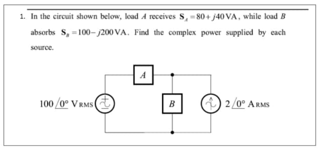
1. In the circuit shown below, load A receives S, 80+ j40 VA, while load B absorbs S, =100-j200 VA. Find the complex power supplied by each source. A 100 /0° V RMS 2/0° ARMS B


Q: HW 10 An integral cycle circuit with source voltage Vs = 100 sin(wt) and resistive load 100, if the…
A: Bartleby has policy to solve only first question and it's first 3 subparts. For the solution of…
Q: The variable load resistor RL in the circuit shown is adjusted for maximum average power transfer to…
A: Applying Thevenin’s theorem , for calculating Thevenin’s voltage by removing load resistance…
Q: 8. Two impedances, Z, = 0.8 + j5.6 Q and Zz = 8 - j16 Q, and a single-phase mot are connected in…
A: In this question we will find complex power for each impedance and total current and total power…
Q: Q.19: For the circuit shown: 1. Find the phasor currents i, & i2? 2. Compute the total power. JIQ…
A:
Q: V) For the circuit shown in the figure answer questions 13 and 14, the voltage value is given in…
A:
Q: For the circuit shown , what value of ZL results in maximum average power transfer to ZL? What is…
A: Given data: Voltage, Vth = 10 V. Resistor, Rth = 3000 Ω. Inductor, Lth = j4000 Ω. According to…
Q: For the circuit show below, solve for the following: a. The complex power delivered to each passive…
A:
Q: 0.052 j0.52 mn Vs 25020°V,m L[1, 41.
A:
Q: Problem 4: For the circuit shown in figure, compute the average power delivered to the load, the…
A:
Q: For the diagram below calculate the Total Real Power (PT),; The Total Reactive Power (QT); the Total…
A:
Q: There is a load formed by the series connection of the resistor R0 and the inductance L0 between the…
A:
Q: 7 A load impedance, Z1 = 10 + j3 2, is connected to a source with line resistance equal to 1 N, as…
A: Hello. Since your question has multiple sub-parts, we will solve the first three sub-parts for you.…
Q: Three loads are connected in parallel across the 50020° volt (rms) source shown below. (a) Calculate…
A: In the system, three loads are connect to parallel of each other's Find the power factor of the…
Q: 4. A 250 V rms system is supplying three parallel loads. One draw 20kW at unity pf, a second uses 25…
A: The circuit has real power, reactive power and the apparent power. The angle of apparent power is…
Q: It is required to know 1. The Real Power of the Generator: 2. The Reactive Power of the Generator 3.…
A: “Since you have posted a question with multiple sub-parts, we will solve the first three sub-parts…
Q: Given for Problem 1: Iç । [+ L₁ L4 Load 1: 200 W, unity power factor Load 2: 1200 W at 0.85 power…
A: As per our policy, we are allowed to attempt only first three part of question remaining post…
Q: In the following circuit: A. Find the power absorbed by Z, if Z, = 2°. B. Find Z, such that it…
A: Given data: ZL=2 Ω
Q: QI/A power plant has to meet the following load demand Load A: 100 MW from 8 AM - 6 PM Load B: 150…
A: The solution can be achieved as follows.
Q: A load operating at 280 V RMS draws 81 A RMS at a power factor 0.97 leading. Find: 1. The real power…
A: Given, Vrms=280 VIrms=81 ACosϕ=0.97 leading
Q: Assume that the voltage applied to a load is V = 2082 – 30° V and the current flowing through the…
A: Complex power S = VI° | S| = Complex power . S SI unit VA COS(theta) = pf. V = 208< -30° V…
Q: Which of the following descriptions IS NOT correct for loads in power systems? A. The purely…
A: capacitive load will deliver reactive power to the grid. so option C is the wrong one
Q: The load impedance absorbs 2.5 kW and generates 5 kVAR. The sinusoidal voltage source develops 7.5…
A: Given The power absorbed by the load impedance PL=2.5 kW The reactive power generates by the load…
Q: For the circuit shown below, determine the apparent power delivered by the source, power dissipated…
A:
Q: What is the value of real power supplied by the source in the figure? 62 30/0° V rms 42 3031.4 2007…
A: Impedance of the circuit :- 6+(4∥(-j2))=6.8-j1.6=6.98∠-13.24o So current supplied by source =…
Q: In the circuit shown below, load A receives S, =80+ j40 VA, while load B absorbs S, =100– j200 VA.…
A:
Q: The apparent power of the load Z1 in the circuit given in the figure | S1 | = 16 kVA and at 0.8 back…
A:
Q: For the circuit shown, what is the complex power, S, consumed by the 18 + 732 load impedance?…
A: To find complex power S by impedance 18 + j 32 ohm
Q: In the circuit shown in figure, calculate VS, the complex power supplied by the source. (X < Y,…
A: From given load we will find current in line. Sending end voltage =receiving end voltage +drop in…
Q: The variable load resistor RL in the circuit shown is adjusted for maximum average power transfer to…
A: From the given circuit the transformation ratio of the given transformer is given as k=21 Thus…
Q: H.W.: A 440 V rms source supplies power to a load ZL = 10 + j2 Q through a transmission line having…
A: As per the guidelines of Bartley we supposed to answer first three subpart only.
Q: (a) The voltage v across a load and the current i into the positive-polarity terminal are as follows…
A: For signal,x(t) = x0+x1Cos(w1t+ϕ1) +x2 COs(w2t+ϕ2)+....RMS value of x(t) = x02+x122+x222+....where…
Q: a) A 140-V rms, 60-Hz source is applied to a load impedance Z. The apparent power entering the load…
A:
Q: A 110-V rms, 60-Hz source is applied to a load impedance Z. The apparent power entering the load is…
A:
Q: In the circuit shown , a load having an impedance of 39+j26 Ω is fed from a voltage source through a…
A:
Q: QI/A power plant has to meet the following load demand: Load A: 100 MW from 8 AM - 6 PM Load B: 150…
A: Plant daily load are given in the table. Plot the daily load curve, diversity factor Load factor…
Q: Exersice 1. Single phase load&compensation 0. l1002 |10+j20 2 Two loads z, = 100 2 and Z2 = 10+j20 Q…
A:
Q: Q2) Two loads connected in parallel are respectively 2Kw at a p.f. of 0.75 leading and 4Kw at a p.f.…
A: In the question Two loads are connected parallel One is 2kW at 0.75 PF leading Second 4kW at…
Q: In the circuit shown , a load having an impedance of 39+j26 Ω is fed from a voltage source through a…
A: From the given circuit the equivalent impedance is given as Thus the total current flowing in the…
Q: Calculate the apparent power, real power, andreactive power for the circuit shown in Figure.Draw the…
A: (a) From the given circuit, Capacitive inductance is given by,
Q: Find the current in z₁ and 22 respectively when they are connected in parallel and supplied by 230…
A: We have an circuit with, Z1 = 3 + j 4 Ω Z2 = 3 - j 4 Ω Voltage Supplied (V) = 230 V = 230 ∠0° And…
Q: Two impedances are fed by a source with V = 100 V rms /160° , as shown below. The total current is I…
A: Circuit is given as, Given data, P1=23.2WQ1=50 Var
Q: A power circuit is shown below. The active and reactive powers of the 3 loads and their types are as…
A:
Q: Determine the average power absorbed by delta connected load Z, = 30+ j27 2. %3D 100/0° V rms j0.5 2…
A:
Q: For the circuit show below, solve for the following: a. The complex power delivered to each passive…
A:
Q: Q1//A power plant has to meet the following load demand: Load A: 100 MW from 8 AM - 6 PM Load B: 150…
A:
Q: LEARNING EXAMPLE f=60HZ,|Vine =34.5kV rms. Required:pf = 0.94leading %3D a Balanced load Balanced 24…
A: The solution is given below
Q: v = 60 sin(wt + 30°) i = 15 sin(wt + 60°) Given the above expressions for voltage and current, find:…
A:
Q: Q2: For the circuit shown below, determine the apparent power delivered by the source, power…
A:
Q: 2. For the circuit show below, solve for the following: a. The complex power delivered to each…
A: Complex Power: Complex power is defined in terms of angle as compared to apparent power which is…

Step by step
Solved in 3 steps with 2 images


- Discuss the future trends and technologies in power systems, such as microgrids and energy storage systems.If the Reactance of the cylindrical rotor machine connected to an infinite bus bar is double that of the external reactance of 0.5.p.u. If the power angle is 35°, real power output is 0.8, compute the excitation voltage, and for the same power output, if the load angle is reduced by 10 degrees, find the external reactance to achieve this.Write the differential equation for t > 0 for iC in the given figure. Assume VS = 9 V, RS = 4 kohm, R1 = 11 kohm, and R2 = R3 = 20 kohm.
- A transmission line has a reactance of 1 Pu is operating at Vs = Vr = 1 Pu. The generator is connected at source end which is delivering 0.5 Pu of active power and the transmission line is compensated with a series capacitance of 0.5 Pu. Find the load angle with series capacitance compensation ?Consider a PV module with the following external parameters at STC: Pmax = 320 W, VOC = 45 V, ISC = 8 A, NOCT =40 °C and the temperature coefficient of power is −1 W/°C. a) If the ambient temperature rises to 35 °C while the irradiance is 1,000 W/m2, what is the cell leveltemperature, calculated with the NOCT model?b) What is the new power output of the PV module under the new ambient temperature of 35 °C and 1,000W/m2irradiance?For the configuration shown in the figure below, determine Zi if Vs = 40 mV, Sense = 0.5 kΩ, and Ii = 20 µA
- How do distributed energy resources (DERs) such as solar panels and wind turbines impact the operation and planning of power systems? Analyze their integration challenges.In a certain circuit supplied from 50 Hz mains, the potential difference has amaximum value of 500V and the current has a maximum value of 10A. At the instantt=0, the instantaneous values of the p.d. and the current are 400V and 4Arespectively, both increasing positively. Assuming sinusoidal variation, statetrigonometrical expressions for the instantaneous values of p.d. and the current attime t. Calculate the instantaneous values at the instant t=0.015s and find the angle ofphase difference between the p.d. and the current. Sketch the phasor diagram (neednot be to scale).For the frequency-domain circuit , calculate: 1. a) the rms magnitude of Vo;2. b) the average power dissipated in the 9 Ω resistor;3. c) the percentage of the average power generated by the idealvoltage source that is delivered to the 9 Ω load resistor.
- S.2) The serial impedance of the 300 km power transmission line is 23 + j75 ohm / phase and the shunt acceptance is j500 microS / phase. A power of 50 MW with a power factor of 0.88 under 220 kV interphase voltage from the end of the power transmission line being shot. Using these data of the energy transmission line, a) Characteristic impedance of the energy transmission line, b) Natural apparent power of the energy transmission line according to the 220 kV interphase operating voltage, c) The values of the line parameters A, B, C and D of the transmission line using hyperbolic functions, d) Calculate the maximum power that the power transmission line can transmit.a) You have been employed as an electrical engineer by a power transmission company to design a short transmission line to supply power to a light-industrial load consumer with power system specification as follows, a 3-ph, 60Hz overhead short transmission line with a line-to-line voltage of 23KV at the load end, line impedance of 2.48 ±j6.57Ω/phase, the industry has a cumulative consumption of 9MW with a power factor of 0.85 of lagging as a result of several induction motor on its production lines.As part of the regulations for connections to the grid, you are to provide justifications and values to the Energy Commission of Ghana.(i) What would be value of the voltage between the live conductor and the neutral, between live and live voltages at the industrial premises of the factory?(ii) What load angle would expect the factory to be operating at?Determine the amount of distributed generation active power that can besafely fed to a 400V line with Z= 0.3 + j0.9 Ω, if the maximum allowablevoltage rise is 4V and reactive power is negligible.