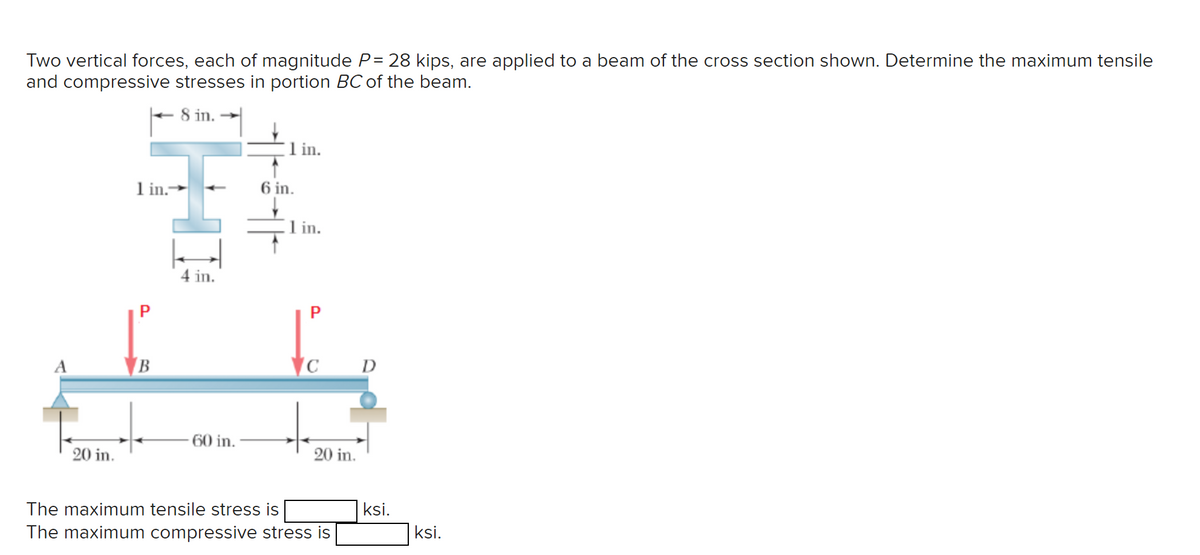
Two vertical forces, each of magnitude P= 28 kips, are applied to a beam of the cross section shown. Determine the maximum tensile and compressive stresses in portion BC of the beam. 8 in.→ 1 in. 1 in.- 6 in. 1 in. B 4 in. P C D 60 in. 20 in. 20 in. The maximum tensile stress is ksi. The maximum compressive stress is ksi.
Q: A steel bar having cross sectional area of 100 П mm² is subjected to a tensile force of 40 kN.…
A:
Q: please provide step by step solutions and draw the lever on the graph as well. i know the answers.…
A: To draw phase drawing to explain the details about microstructures
Q: The diameter of the eye of a stationary hurricane is 20 mi and the maximum wind speed is 100 mi/h at…
A:
Q: (a) derive equations for the shear force V and the bending moment M for any location in the beam.…
A: (a) derive equations for the shear force V and the bending moment M for any location in the beam.…
Q: The pulley system shown is at rest when the motor M starts pulling in rope so as to lift the 120lb…
A: Given:The value of The weight of the cargo, The speed of cargo after ,
Q: Not Ai generated answers, I need to understand please show all steps.
A: FINAL ANSWER: Rayleigh number for air= 817.47Rayleigh number for Helium= 14.09Rayleigh number for…
Q: Q4) Determine the velocity of cart A if cylinder B has a downward velocity of 2 m/sec at the instant…
A:
Q: A hollow shaft with an outside diameter of 3.2 in. and an inside diameter of 2.6 in. is subjected to…
A: The ans is given below please have a look.Explanation:
Q: A distributed load is applied to beam AB, shown in the diagram below. The beam is supported by a…
A: Draw FBD
Q: A cylinder of mass m and mass moment of inertia JO rolls without slipping on the ground and is…
A: The cylinder rolls without slipping in the ground.
Q: Problem 7-41: The simply supported beam is built up from three boards by nailing them together as…
A: The step by step solution is provided below.
Q: Consider a pulley system shown below. The coordinate x is the displacement of G. Assume there is no…
A:
Q: A heavy machine, weighing 3000 N rest on a rubber mount modeled as a stiffness k and a damper c. The…
A: Given:The weight of the machine, The stiffness of the system is The damping coefficient is The…
Q: Determine the stress resultants N(x), V(x), M(x) and draw the diagrams of the stress resultants and…
A: Answer and explanation provided on the picture uploaded. please dont forget to rate positively.…
Q: About Industrial Pipes and based on a hypothetical industrial piping system: How to estimate…
A: The objective of the question is to understand the process of estimating corrosion thickness,…
Q: t = 0, the mass is released at x(0) = x0 > 0 and x(0) = 0, find the condition for =vo, vo such that…
A:
Q: 1) The hotter fluid of a parallel flow heat exchanger decreases in temperature from 200°C to 100°C…
A:
Q: Locate all the instantaneous centers of the mechanism shown below: OB₂ = 20 cm, 020₁ = 15 cm, OC =…
A: The solution is given below.Explanation:Approach to solving the question: Detailed…
Q: Make a schematic drawing of a hypothetical piping system with: Power Sources: Boiler Energy…
A: DiagramExplanation:Step 1:Step 2:Step 3:Step 4:
Q: What would the full-body diagram of this boom be?
A:
Q: If the allowable shear strength of aluminum is 45 MPa, determine the minimum thickness, t, of the…
A:
Q: A distributed load is applied to beam AB, shown in the diagram below. The beam is supported by a…
A: Draw FBD
Q: Name: Surname: Student ID: ME 216 MECHANICS OF MATERIALS QUIZ # 2 QUESTION σ (MPa) 490 420 350 280…
A: According to our guidelines, we are supposed to answer the first three sub parts, Please repost…
Q: please help me with my homework. please provide brief explination , many thanks for your time
A: Using formula for Cn we can obtain the required expression and draw spectrumExplanation:Step 1:Step…
Q: For the mechanism shown below, the hydraulic cylinder DB extends with a constant velocity of vg =…
A: The velocity of point B is
Q: 9.11 A strain gauge, diaphragm pressure transducer (accuracy: <0.1% reading) is subjected to a…
A: The design uncertainty for the voltmeter.The design uncertainty for the strain gage is-Write the…
Q: Equilibrium of Force Systems Q11) Find the reaction moment at the built-in support at A due to the…
A: Find the reaction moment at the built-in support at A due to the applied loadings as shown in figure…
Q: Parvinbhai
A: The objective of the question is to determine the natural frequency of the system given the static…
Q: A syringe, containing an incompressible fluid, is oriented vertically and the plunger is slowly…
A: To determine:At point 3,the potential energy due to pressure
Q: into steam at 115.0 °C. (Hint: make a sketch of the water heating curve before you start.) # 11.…
A:
Q: The 20-g bullet is travelling at 400 m/s when it becomes embedded in the 2-kg stationary block. The…
A:
Q: 4. Solve problem 8.10 in our textbook (find the safety factor for failure at the fillet). Note that…
A:
Q: For a hollow shaft of external and internal diameters 10 cm and 4 cm respectively, the torsional…
A: Given data :- D=Outer diameter =10cmd=Inner diameter =4cmCalculate :- Polar modulus is defined as…
Q: The diameter of the eye of a stationary hurricane is 20 mi and the maximum wind speed is 100 mi/h at…
A:
Q: A proposed wind farm installation is based on the use of thirty 2 MW wind turbines. The installed…
A: The objective of the question is to calculate the cost of energy produced by a proposed wind farm.…
Q: The diameter of the eye of a stationary hurricane is 20 mi and the maximum wind speed is 100 mi/h at…
A: Given:The wind speed at the eye wall, , The wind speed at the eye wall, ,
Q: For the Figure below, Calculate the second moment of area about the Y- axis. Express your answer as…
A: Please refer explanationExplanation:Step 1: Step 2: Step 3: Step 4:
Q: For the mechanisms shown below determine the number of links, full joints, half joints and the…
A: “Since you have posted multiple questions, we will provide the solution only to the first question…
Q: Determine (a) the magnitude and (b) direction of the anchoring force needed to hold the horizontal…
A:
Q: The top rotates with a constant angular velocity of 40 rad/s about its axis which is inclined in the…
A: 40(−16i^+15j^)=v^(402)(−16i^−15j^)=aExplanation:Step 1:We will utilize vector calculus to…
Q: 200 mm m 15 kg C-40 N-5/m TTTTT Fig. 1 K-300 N/m 100 mm
A: Mass =15kgC= 40 N-s/mK= 300 N/m
Q: A uniform electric field of magnitude 260 V/m is directed in the positive x direction. A +15.0 μC…
A: The objective of the question is to find the change in the potential energy of the charge-field…
Q: 5.48 The hydraulic dredge shown in Fig. P5.48 is used to dredge sand from a river bottom. Estimate…
A: The specific gravity of the sand/water mixture is: SG = 1.2The diameter of the hydraulic dredge pipe…
Q: = Air flows radially outward between the two parallel circular plates shown in the figure below. The…
A:
Q: ! Required information A helical compression spring is made of hard-drawn spring steel wire of…
A: helical compression Explanation:Step 1:Step 2:Step 3:Step 4:
Q: A mass weighing 16 pounds stretches a spring 83 feet. The mass is initially released from rest from…
A:
Q: E 4 kN B PROBLEM 5.44 Draw the shear and bending-moment diagrams for the beam and loading shown, and…
A: Draw the shear and bending-moment diagrams for the beam and loading shown, and determine the maximum…
Q: A 0.5 m-long metal composite shaft AB consists of a steel rod (radius r=25 mm), the outer surface of…
A: Answer and explanation are given below.Explanation: Please let me know if there are any further…
Q: SITUATION 5: The hook shown in the Fig. SRB-004 is subjected to three forces A, B, and C. If A = 8…
A:
Q: See Image
A: modeExplanation:Step 1:Step 2:Step 3:Step 4:
Step by step
Solved in 1 steps with 2 images
- The rigid beam BC is supported by rods (1) and (2). The cross-sectional area of rod (1) is 7 mm2. The cross-sectional area of rod (2) is 18 mm2. For a uniformly distributed load of w = 2.7 kN/m, determine the length a so that the normal stress is the same in each rod. Assume L = 5.65 m.A body is subjected to a direct tensile stress of 300 MPa in one plane accompained by a simple shear stress of 200 MPa. Determine maximum normal stress on the plane.The cross-sectional area of bar ABCD is 600 mm2. Determine the maximum normal stress in the bar.
- A cylindrical tank steel pressure vessel 200mm in radius and 4.0m in length, is subjected to an internal pressure of 3.0 MPa. Determine the thickness of tank (nearest mm) if the following stresses are not to be exceeded: tangential stress of 45 MPa and longitudinal stress of 30 MPa. and also show the free body diagramTwo vertical forces are applied to the beam of the cross section shown. Determine the maximum tensile and compressive stresses in portion BC of the beam.1. Determine the stresses for a square stress element on top of CD at point D. The stress element is aligned with CD. Then determine the maximum normal and maximum shear stress at the same point for the stress element. CD is 36 mm in diameter and BC is 24 mm diameter. Both are solid. 2. For the beam shown determine the stress for a stress element on top, similar to point H, but at the wall A instead (centered on top at the wall). Then determine the maximum normal and shear stress for that stress element.
- For a steel rod with a circular cross section with a diameter of D = 20 mm, the following is required: 1. Draw a diagram of the longitudinal force 2. Draw a diagram of normal stresses 3. Determine the total elongation of the rod if Е = 2∙10^5 MPa When calculating, take: а = 2 m, b =1.2 m, F=10 кN - The point of application of force! The work must be done on one sheet of A4 paper, which must show: - Using the method of sections to determine the longitudinal forces in the rod. - Draw a diagram of longitudinal forces N - Determination of normal stresses based on the constructed plot of longitudinal forces. - Draw diagram a normal stresses - Determination of the full extension of the rodIn a 2.5 cantilevered I-beam, 2500 kg weight is applied at 0.75 meter from the free end. If the allowable stress in beam is 120 Mpa, determine the section modulus and The base and height of the beam if the base is 75% of its height mm.Two vertical forces, each of magnitude P = 22 kips, are applied to a beam of the cross section shown. Determine the maximum tensile and compressive stresses in portion BC of the beam. The maximum tensile stress is ksi. The maximum compressive stress is ksi.
- A steel pipe 120 mm external diameter and 60 mm internal diameter is subjected to an internal pressure of 15 N/mm2 and an external pressure of 5 N/mm2. Determine and sketch curves showing the distribution of the radial and circumferential stress across the section using Lame’s equations.A load P is supported by a structure consisting of rigid bar ABC, two identical solid bronze [E= 15,000 ksi] rods, and a solid steel [E= 30,000 ksi] rod. The bronze rods (1) each have a diameter of 0.625 in. and they are symmetrically positioned relative to the center rod (2) and the applied load P. Steel rod (2) has a diameter of 0.375 in. If all bars are unstressed before the load P is applied, determine the normal stresses in the bronze and steel rods after a load of P= 14 kips is applied.A thick cylinder internal diameter 240mm external diameter 240mminternal diameter ‘D’ is subject to external pressure of 40MPa. Determine the diameter‘D’ if the minimum hoop stress in the cylinder is not to exceed 200MPa in mm.