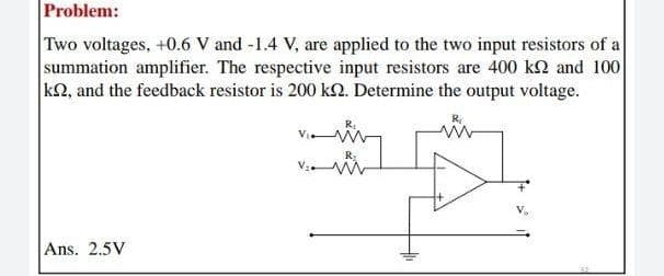
Two voltages, +0.6 V and -1.4 V, are applied to the two input resistors of a summation amplifier. The respective input resistors are 400 k2 and 100 kN, and the feedback resistor is 200 kN. Determine the output voltage. Ans. 2.5V


Q: What must the voltage at the inverting input of the op- amp be? What is the voltage drop across Rin?…
A:
Q: The inverting OP-AMP shown in the figure has an open loop gain of 100. The closed loop gain VV, is…
A: Referring to the given circuit, the negative terminal of the op-amp is known as the inverting…
Q: Draw the circuit diagram of an op-amp voltage follower. What value is its voltage gain? Input…
A: Circuit diagram of voltage follower circuit is given by, In voltage follower circuit input voltage…
Q: For an ideal non-inverting amplifier, what will happen to the gain if the feedback resistor is equal…
A:
Q: Consider the series-shunt feedback amplifier of Figure below. Assume that the voltage divider (R1,…
A: Given : Series Shunt Feedback Amplifier Voltage divider R1,R2 is implemented with 1M ohm…
Q: 3. Inverting Amplifier is a normal OP-Amp in which the output is given as feedback with a feedback…
A:
Q: (a) An audio amplifier is to be designed to develop a 50-V peak-to-peak sinusoidal signal at a…
A: Peak to peak voltage is given 50 V Therefore, Frequency is given
Q: Given circuit shown below, assume ideal components. Find the value of IA and resistor, R. What is…
A: The circuit diagram is shown below:
Q: An ideal operational amplifier circuit in the closed-loop negative-feedback configuration is shown…
A: Given Data: Is = 3 mA Rs = 3 kohm
Q: (a) Determine the equivalent resistance Ri' (b) Determine the current gain Ais=Io/ls. (c) Determine…
A:
Q: 02 (B):- For the non-inverting operational amplifier circuit shown in Figure (3). 1) Derive the…
A:
Q: Sketch the transfer characteristics of OP-AMP with input offset voltage equal to 4 mV.
A: Let op-amp is ideal, so gain will be infinite input offset voltage Vi/o=±4 mV
Q: P2.24 A two-transistor series voltage feedback amplifier is shown in Figure P2.24(a). This AC…
A: Given: A two-transistor series voltage feedback amplifier is shown below: A block diagram…
Q: For the op-amp shown in the following figure, the unity-gain bandwidth has the value of 20.5 KHz.…
A:
Q: For the op-amp shown in the following figure, the purpose of R1 and R2 is- R2 R1 Select one: O a. to…
A: For given amplifier circuit voltage error occurs in the output voltage due to bias current.
Q: What are the nominal, minimum, and maximum values of the open-loop gain at 25◦C for an OP-27…
A: Given TA = 25◦ C, Supply voltage of the amplifier Calculating nominal value of the open loop gain
Q: Q.3 For the circuit shown in Figure Q3 find (a) the loading effect of the feedback circuit at the…
A: Since you have posted a question with multiple sub-parts, we will solve the first three subparts for…
Q: Calculate the closed-loop voltage gain, ACL, of an inverting op-amp circuit having an input…
A:
Q: Assuming the op amp to be ideal, derive an expression for the closed-loop gain of the circuit shown…
A:
Q: 4. What is the voltage gain of an inverting op-amp in which the feedback resistor has a value of…
A: Given data, An inverting op-amp in which Rf=7000 ΩRin=1500 Ω
Q: For the series-series feedback amplifier in right figure, find the value of RE, The feedback gain,…
A: For a current-series or series-series amplifier using BJT, the following data is given. RC=2.2 kΩ,…
Q: find the gain of inverting amplifier it takes 30 volt input supply voltage, input resistance of 40…
A: Given: Input voltage = 30 volt Input resistance =Ri=40Ω Feedback resistance =Rf=80Ω
Q: 2: P01C_Q30 For the ideal OP-Amp in negative feedback configuration shown in Figure Q30, calculate…
A: The given circuit is, Here, R1=10 kΩ, R2=5 kΩ, R3=2 kΩ, R4=2 kΩ, R5=5 kΩ, R6=1 kΩ and RL=10 kΩ
Q: 1- Mention any two non linear applications of op-amp.
A: As per the guidelines, we supposed to answer one question at a time so please ask other questions…
Q: An amplifier circuit has an overall current gain of -100 and an input resistance of 10 kn with a…
A: Given an amplifier circuit has, An overall current gain, AI=-100 Input resistance, Ri=10 kΩ Load…
Q: Homework: For the comparator circuit shown below sketch the Hysteresis Curve showing Transfer…
A:
Q: A- The point where amplifier high frequency gain has dropped 30% is a. the crossover point. b. the…
A: The point where amplifier high frequency gain has dropped 30% is called cross over point.
Q: Assume that the R2/R1 ratio of a feedback amplifier with voltage supply of +/- 10 V is 3.4 and that…
A: Assume that the R2/R1 ratio of a feedback amplifier with voltage supply of +/- 10 V is 3.4 and that…
Q: 9- Results and Discussion:- 1-what are the differences between the inverting and non-inverting…
A: These are the questions related to the operational amplifier and it's types as well as various…
Q: When 100 V and 20 V are applied to the non inverting and the inverting terminal of open loop an…
A: For an open-loop operational amplifier, if Ad and Ac represents the differential gain and…
Q: For the series-series feedback amplifier in right figure, find the value of Rg, The feedback gain,…
A: The series-series feedback amplifier has Rc=2200 Ω, hfe=20, hie=1500 Ω, Vi=4.8 mV, Io=120 μA.
Q: Activity 2: You are asked to examine the performance of three op-amp circuits. 2-A) Categorize the…
A: 2-a) Circuit A : This op amp doesn't contain any feedback. It is connected in open loop. Circuit B…
Q: 1- Mention any two non linear applications of op- amp.
A: As per the guidelines, we supposed to answer one question at a time so please ask other questions…
Q: Consider the series-shunt feedback amplifier of Figure below. Assume that the voltage divider (R1,…
A:
Q: Mention the characteristics of instrumentation amplifier using opamp What are the applications of…
A: Instrumentation amplifier contain three op-amp. Out of 3, two will be inverting amplifier and third…
Q: Sketch the transfer characteristics of OP-AMP with input offset voltage equal to 4mV
A: Let Op amp is ideal, so gain will be infinite Input offset voltage Vio = +- 4mV
Q: Consider the series-shunt feedback amplifier of Figure below. Assume that the voltage divider (R1,…
A: Given the series-shunt feedback amplifier in the figure. And also given the value RD =10 ohm, close…
Q: Find the value of output voltage and closed loop gain of inverting amplifier if input voltage is 50…
A: Given: Input voltage = 50mV Input resistance = Ri=47kΩ Feed back resistance =Rf=10 MΩ
Q: Assume that the R2/R1 ratio of a feedback amplifier with voltage supply of +/- 10 V is 3.0 and that…
A: Solve the problem
Q: Q4. Figure 4 shows a circult diagram of the Wien-bridge oscillator. ASsume that the amplifier…
A: a) Barkhausen's Criteria for sustained oscillator 1) Magnitude of loop gain should be unity. i.e.…
Q: gain of 10 is required from a noninverting constant-multiplier op-amp circuit. If the input resistor…
A: We need to find out the value of feedback resistance for given amplifier
Q: 2) The circuit shown below uses a diode in the feedback path of the op amp. For each question, use…
A:
Q: Q2/B)- Show the connection of three combination op-amp stages ( Parallel and series connection)…
A: Gain of 1st stage is +110 It means op-amp in 1st stage must be non-inverting amplifier.…
Q: (b) Choose appropriate resistance values for the two resistors R₁ and R2 for an expected voltage…
A: Given the circuit, as shown below: b) We need to choose appropriate resistance values for the two…
Q: 3F roblem 1. (P1) Three op-amps are connected in cascade configuration. An 80 microVolts signal is…
A:
Q: A positive-feedback amplifier circuit (inverting Schmitt trigger) is shown in the following figure.…
A:
Q: An opamp is working as both inverting and non inverting amplifier then examine it's performance by…
A: Performance of OP amp is obtained considering different parameters such as input voltage, input…
Q: For the ideal OP-Amp in negative feedback configuration shown in Figure Q30, calculate the…
A: Given circuit, Where, R1=10 KΩR2=5 KΩR3=2 KΩR4=2 KΩR5=5 KΩR6=1 KΩRL=10 KΩ


Trending now
This is a popular solution!

Step by step
Solved in 2 steps with 1 images

- An inverting op – amplifier stage is designed with an input resistance of 5 KΩ and feedback resistance of 10 KΩ. The load resistance is 100 Ω with DC gain of 5x10^4 . The output internal resistance is 500 Ω while the input impedance is infinity, assuming an input voltage of 1.5 volts, calculate the following ?a) The AC gain ?b) The output voltage ?c) The looking back resistance ?Amplifirs Given that a feedback network is shunt-series, and the output load is 10kΩ, what is the output voltage across it given that the transfer gain is 10, the source current is 20mA and the feedback current is 10mA?1. A non-inverting op-amp circuit has the open loop gain of 105 and the resistances R1 = 1k Ω and R2 = 39k Ω . Calculate (a) The actual value of voltage gain, (b) Considering the finite open loop gain, the ideal value of gain, and (c) The percentage error, when ideal voltage gain is compared with actual voltage gain.
- Assume for a moment that perfectly accurate resistors were available for feedback networks; that is resistor tolerance is 0%. Then any deviation from the value set by the feedback resistor ratio is caused by insufficient raw op-amp gain. What minimum raw gain would be needed to get within 1% if an intended overall gain of 10? What if the intended gain is 100 instead?Q2/B)- Show the connection of three combination op-amp stages ( Parallel and series connection) using an LM348 IC to provide outputs that are 110, 400, and 2601 times larger than the input. Use a feedback resistor of Rf = 500 k? in all stages, while can use only (R= 50 k? for first stage), (R= 25 k? for second stage), and (R= 10 k? for third stageDraw the circuit of 3 op-amp configuration of instrumentation amplifier andderive the gain equation. Consider all internal resistors to be equal.
- Please answer this two part question A) It is known that when an Op-amp is operated using the negative feedbackconfiguration, the output impedance reduces. Derive an expression that proves this. B) It is known that when an Op-amp is operated using the positive feedbackconfiguration, the output impedance increase. Derive an expression that proves this.Given in the figure is a two-stage amplifier design that employs negative feedback. Answer the following questions. Use the notation (R1 + R2 + ... + Rn) for series resistors and (R1 || R2 || ... || Rn) for parallel resistors for clarity and ease. Assume that the transistors are already biased properly in the saturation region and ro1 = ro2 → ∞. Also assume that the capacitors have infinite capacitance. 1.) Find the expression for the open loop gain Av 2.) Derive the resistance Rin which is the resistance that can be seen at the input port of the amplifierSuppose the op amp shown has an fT of 1 MHz. What is the phase margin of the amplifier?
- A noninverting amplifier is being designed to have a closed-loop gain of 36 dB. What op-amp gain is required to have the gain error less than 0.15 percent?A certain op-amp has three internal amplifier stages with midrange gains of 30 dB, 40 dB, and 20 dB. Each stage also has a critical frequency associated with it as follows: fc1 = 600 Hz, fc2 = 50 kHz, and fc3 = 200 kHz. (a) What is the midrange open-loop gain of the op-amp, expressed in dB? (b) What is the total phase shift through the amplifier, including inversion, when the signal frequency is 10 kHz?Which op-amp network is commonly used to reduce the effect of noise on comparator circuits (Schmitt trigger arrangement)?Using an output networkUsing a negative feedback networkUsing an input networkUsing a positive feedback network