upport at C. The beam carries a uniformly distributed load (UDL) of 5 kN/m across ection B to C and a concentrated load of 25 kN at D. Show the Free Body Diagram (FBD) of the beam then determine the reaction force. Calculate the shear force, V. Draw Shear Force Diagram (SFD). Calculate the bending moment, M. Draw the Bending Moment Diagram (BMD). 25 kN 5 kN/m D В ´ 2 m. 4 m 4 m
upport at C. The beam carries a uniformly distributed load (UDL) of 5 kN/m across ection B to C and a concentrated load of 25 kN at D. Show the Free Body Diagram (FBD) of the beam then determine the reaction force. Calculate the shear force, V. Draw Shear Force Diagram (SFD). Calculate the bending moment, M. Draw the Bending Moment Diagram (BMD). 25 kN 5 kN/m D В ´ 2 m. 4 m 4 m

Principles of Foundation Engineering (MindTap Course List)
8th Edition
ISBN:9781305081550
Author:Braja M. Das
Publisher:Braja M. Das
Chapter6: Vertical Stress Increase In Soil
Section: Chapter Questions
Problem 6.4P: Refer to Figure P6.4. A strip load of q = 900 lb/ft2 is applied over a width B = 36 ft. Determine...

Related questions

Question
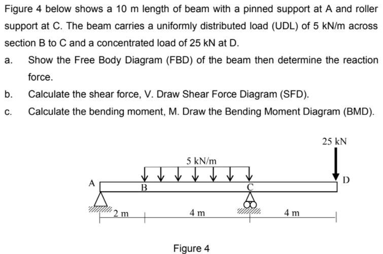
Figure 4 below shows a 10 m length of beam with a pinned support at A and roller
support at C. The beam carries a uniformly distributed load (UDL) of 5 kN/m across
section B to C and a concentrated load of 25 kN at D.
a. Show the Free Body Diagram (FBD) of the beam then determine the reaction
force.
b. Calculate the shear force, V. Draw Shear Force Diagram (SFD).
c. Calculate the bending moment, M. Draw the Bending Moment Diagram (BMD).
Transcribed Image Text:Figure 4 below shows a 10 m length of beam with a pinned support at A and roller
support at C. The beam carries a uniformly distributed load (UDL) of 5 kN/m across
section B to C and a concentrated load of 25 kN at D.
а.
Show the Free Body Diagram (FBD) of the beam then determine the reaction
force.
b.
Calculate the shear force, V. Draw Shear Force Diagram (SFD).
С.
Calculate the bending moment, M. Draw the Bending Moment Diagram (BMD).
25 kN
5 kN/m
D
A
´ 2 m
4 m
4 m
Figure 4
Expert Solution
This question has been solved!
Explore an expertly crafted, step-by-step solution for a thorough understanding of key concepts.

Step by step
Solved in 2 steps with 2 images

Knowledge Booster


Learn more about
Need a deep-dive on the concept behind this application? Look no further. Learn more about this topic, civil-engineering and related others by exploring similar questions and additional content below.Recommended textbooks for you
Principles of Foundation Engineering (MindTap Cou…
Civil Engineering
ISBN:
9781305081550
Author:
Braja M. Das
Publisher:
Cengage Learning
Principles of Foundation Engineering (MindTap Cou…
Civil Engineering
ISBN:
9781305081550
Author:
Braja M. Das
Publisher:
Cengage Learning