ure 5 shows a current series feedback amplifier. The sampled current signal but current, I, flowing in resistor, Rg, where it develops a feedback signal vo cross the resistor, Rg. Determine: Vf the feedback gain, B = 's Io the gain without feedback, A = Vs A the gain with feedback, Af 1+BA RL RE
ure 5 shows a current series feedback amplifier. The sampled current signal but current, I, flowing in resistor, Rg, where it develops a feedback signal vo cross the resistor, Rg. Determine: Vf the feedback gain, B = 's Io the gain without feedback, A = Vs A the gain with feedback, Af 1+BA RL RE

Power System Analysis and Design (MindTap Course List)
6th Edition
ISBN:9781305632134
Author:J. Duncan Glover, Thomas Overbye, Mulukutla S. Sarma
Publisher:J. Duncan Glover, Thomas Overbye, Mulukutla S. Sarma
Chapter12: Power System Controls
Section: Chapter Questions
Problem 12.3P

Related questions
Question
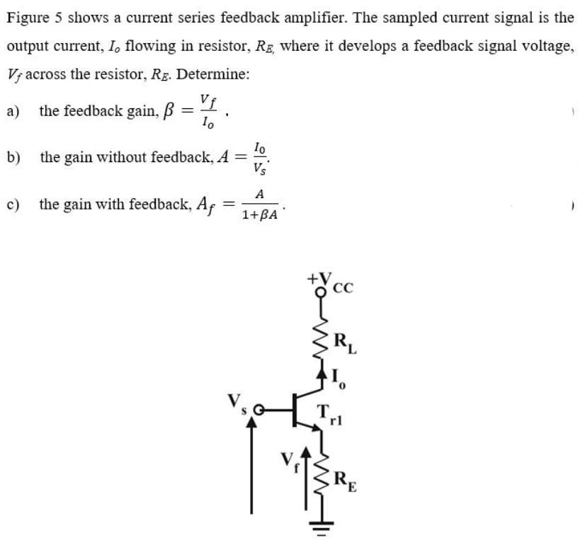
Transcribed Image Text:Figure 5 shows a current series feedback amplifier. The sampled current signal is the
output current, I, flowing in resistor, Rg, where it develops a feedback signal voltage,
V; across the resistor, Rg. Determine:
Vi.
a) the feedback gain, B
1.
:
Io
the gain without feedback, A =
Vs
b)
A
c) the gain with feedback, Af
1+BA
+V
Expert Solution
This question has been solved!
Explore an expertly crafted, step-by-step solution for a thorough understanding of key concepts.

Step by step
Solved in 2 steps with 2 images

Knowledge Booster


Learn more about
Need a deep-dive on the concept behind this application? Look no further. Learn more about this topic, electrical-engineering and related others by exploring similar questions and additional content below.Recommended textbooks for you
Power System Analysis and Design (MindTap Course …
Electrical Engineering
ISBN:
9781305632134
Author:
J. Duncan Glover, Thomas Overbye, Mulukutla S. Sarma
Publisher:
Cengage Learning
Power System Analysis and Design (MindTap Course …
Electrical Engineering
ISBN:
9781305632134
Author:
J. Duncan Glover, Thomas Overbye, Mulukutla S. Sarma
Publisher:
Cengage Learning