Use the information given in the figure below. When the supporting posts are removed, calculate the magnitude of the following: the torque on each side and the net torque of the balancing beam.
Use the information given in the figure below. When the supporting posts are removed, calculate the magnitude of the following: the torque on each side and the net torque of the balancing beam.

International Edition---engineering Mechanics: Statics, 4th Edition
4th Edition
ISBN:9781305501607
Author:Andrew Pytel And Jaan Kiusalaas
Publisher:Andrew Pytel And Jaan Kiusalaas
Chapter9: Moments And Products Of Inertia Of Areas
Section: Chapter Questions
Problem 9.13P: Figure (a) shows the cross section of a column that uses a structural shape known as W867...

Related questions
Question
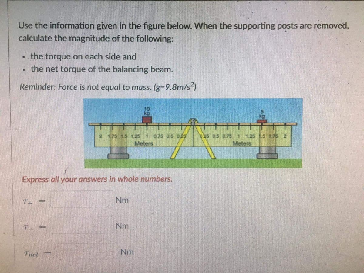
Transcribed Image Text:Use the information given in the figure below. When the supporting posts are removed,
calculate the magnitude of the following:
the torque on each side and
the net torque of the balancing beam.
Reminder: Force is not equal to mass. (g=9.8m/s²)
175 15 1251075 05 029
Meters
ozs as o7s 125
Meters
Express all your answers in whole numbers.
T+
Nm
Nm
Tnet
Nm
Expert Solution
This question has been solved!
Explore an expertly crafted, step-by-step solution for a thorough understanding of key concepts.

Step by step
Solved in 2 steps with 2 images

Recommended textbooks for you
International Edition---engineering Mechanics: St…
Mechanical Engineering
ISBN:
9781305501607
Author:
Andrew Pytel And Jaan Kiusalaas
Publisher:
CENGAGE L
International Edition---engineering Mechanics: St…
Mechanical Engineering
ISBN:
9781305501607
Author:
Andrew Pytel And Jaan Kiusalaas
Publisher:
CENGAGE L