Using the circuit of Figure 2.1 with RII k, R2 -2.2k, R3 = 3.6 k, andE-9 volts, determine the theoretical current and record it in Table 2.1. Construct the circuit. Set the DMM to read DC current and insert it in the circuit at point A. Remember, ammeters goin-line and require the circuit to be opened for proper measurement. The red lead should be placed closer to the positive source terminal. Record this current in Table 2.1. Repeat the current measurements at points B and C. Using the theoretical current found in Step 1, apply Ohm's law to determine the cxpected voltage drops across RI, R2, and R3. Record these valucs in the Theory column of Table 2.2.
Using the circuit of Figure 2.1 with RII k, R2 -2.2k, R3 = 3.6 k, andE-9 volts, determine the theoretical current and record it in Table 2.1. Construct the circuit. Set the DMM to read DC current and insert it in the circuit at point A. Remember, ammeters goin-line and require the circuit to be opened for proper measurement. The red lead should be placed closer to the positive source terminal. Record this current in Table 2.1. Repeat the current measurements at points B and C. Using the theoretical current found in Step 1, apply Ohm's law to determine the cxpected voltage drops across RI, R2, and R3. Record these valucs in the Theory column of Table 2.2.

Introductory Circuit Analysis (13th Edition)
13th Edition
ISBN:9780133923605
Author:Robert L. Boylestad
Publisher:Robert L. Boylestad
Chapter1: Introduction
Section: Chapter Questions
Problem 1P: Visit your local library (at school or home) and describe the extent to which it provides literature...

Related questions
Question
100%
Help please
Transcribed Image Text:Schematics
B
R1
R3
Figure 2.1
I.aboratury Manual fur Circuits Lab
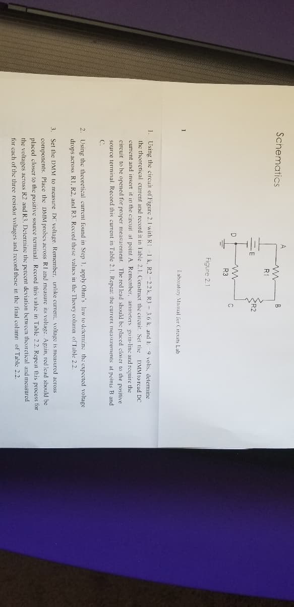
1. Using the circuit of Figure 2.1 with RI
1 k. R2 -2.2 k. R3 = 3.6 k. and E
the theoretical current and record it in Table 2.1. Construct the circuit. Set the
9 volts, determine
DMM to read DC
current and insert it in the circuit at point A. Remember, ammeters goin-line and require the
circuit to be opened for proper measurement. The red lead should be placed closer to the positive
source terminal. Record this current in Table 2.1. Repeat the current measurements at points B and
C.
2. Using the theoretical current found in Step 1, apply Ohm's law to determine the expected voltage
drops across R1, R2, and R3. Record these values in the Theory column of Table 2.2.
3. Set the DMM to measure DC voltage. Remember, unlike current, voltage is measured across
components. Place the DMM probes across RI and measure its voltage. Again, red lead should be
placed closer to the positive source terminal. Record this value in Table 2.2. Repeat this process for
the voltages across R2 and R3. Determine the percent deviation between theoretical and measured
for cach of the three resistor voltages and record these in the final column of Table 2.2.
Transcribed Image Text:6. To find VAC, place the red probe on point A and the black probe on point C. Similarly, to find VB.
place the red probe on point B and the black probe on ground. Record these values in Table 2.3 with
deviations.
Simulation
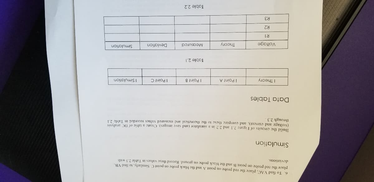
Build the circuits of Figure 2.1 and 2.2 in a simulator (and save images). Create a table of DC analysis
(voltage and current), and compare these to the theoretical and measured values recorded in Table 2.1
through 2.3
Data Tables
I Theory
I Point A
I Point B
I Point C
| Simulation
Table 2.1
Simulation
Theory
Measured
Deviation
Voltage
R2
R3
Table 2.2
Expert Solution
This question has been solved!
Explore an expertly crafted, step-by-step solution for a thorough understanding of key concepts.

This is a popular solution!

Trending now
This is a popular solution!

Step by step
Solved in 3 steps with 2 images

Knowledge Booster


Learn more about
Need a deep-dive on the concept behind this application? Look no further. Learn more about this topic, electrical-engineering and related others by exploring similar questions and additional content below.Recommended textbooks for you
Introductory Circuit Analysis (13th Edition)
Electrical Engineering
ISBN:
9780133923605
Author:
Robert L. Boylestad
Publisher:
PEARSON

Delmar's Standard Textbook Of Electricity
Electrical Engineering
ISBN:
9781337900348
Author:
Stephen L. Herman
Publisher:
Cengage Learning

Programmable Logic Controllers
Electrical Engineering
ISBN:
9780073373843
Author:
Frank D. Petruzella
Publisher:
McGraw-Hill Education
Introductory Circuit Analysis (13th Edition)
Electrical Engineering
ISBN:
9780133923605
Author:
Robert L. Boylestad
Publisher:
PEARSON
Delmar's Standard Textbook Of Electricity
Electrical Engineering
ISBN:
9781337900348
Author:
Stephen L. Herman
Publisher:
Cengage Learning
Programmable Logic Controllers
Electrical Engineering
ISBN:
9780073373843
Author:
Frank D. Petruzella
Publisher:
McGraw-Hill Education

Fundamentals of Electric Circuits
Electrical Engineering
ISBN:
9780078028229
Author:
Charles K Alexander, Matthew Sadiku
Publisher:
McGraw-Hill Education

Electric Circuits. (11th Edition)
Electrical Engineering
ISBN:
9780134746968
Author:
James W. Nilsson, Susan Riedel
Publisher:
PEARSON

Engineering Electromagnetics
Electrical Engineering
ISBN:
9780078028151
Author:
Hayt, William H. (william Hart), Jr, BUCK, John A.
Publisher:
Mcgraw-hill Education,