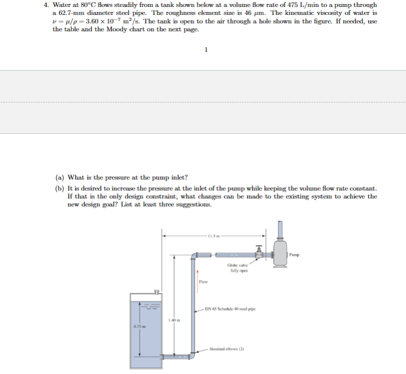
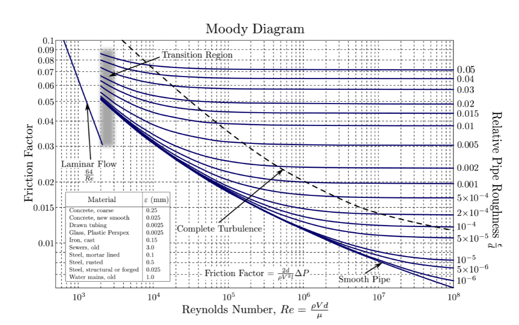
Water at 80◦C flows steadily from a tank shown below at a volume flow rate of 475 L/min to a pump through a 62.7-mm diameter steel pipe. The roughness element size is 46 μm. The kinematic viscosity of water is ν = μ/ρ = 3.60 × 10⁻⁷ m2/s. The tank is open to the air through a hole shown in the figure. If needed, use the table and the Moody chart on the next page. (a) What is the pressure at the pump inlet? (b) It is desired to increase the pressure at the inlet of the pump while keeping the volume flow rate constant. If that is the only design constraint, what changes can be made to the existing system to achieve the new design goal? List at least three suggestions
Water at 80◦C flows steadily from a tank shown below at a volume flow rate of 475 L/min to a pump through a 62.7-mm diameter steel pipe. The roughness element size is 46 μm. The kinematic viscosity of water is ν = μ/ρ = 3.60 × 10⁻⁷ m2/s. The tank is open to the air through a hole shown in the figure. If needed, use the table and the Moody chart on the next page. (a) What is the pressure at the pump inlet? (b) It is desired to increase the pressure at the inlet of the pump while keeping the volume flow rate constant. If that is the only design constraint, what changes can be made to the existing system to achieve the new design goal? List at least three suggestions

Elements Of Electromagnetics
7th Edition
ISBN:9780190698614
Author:Sadiku, Matthew N. O.
Publisher:Sadiku, Matthew N. O.
ChapterMA: Math Assessment
Section: Chapter Questions
Problem 1.1MA

Related questions

Question
Water at 80◦C flows steadily from a tank shown below at a volume flow rate of 475 L/min to a pump through
a 62.7-mm diameter steel pipe. The roughness element size is 46 μm. The kinematic viscosity of water is
ν = μ/ρ = 3.60 × 10⁻⁷ m2/s. The tank is open to the air through a hole shown in the figure. If needed, use
the table and the Moody chart on the next page.
a 62.7-mm diameter steel pipe. The roughness element size is 46 μm. The kinematic viscosity of water is
ν = μ/ρ = 3.60 × 10⁻⁷ m2/s. The tank is open to the air through a hole shown in the figure. If needed, use
the table and the Moody chart on the next page.
(a) What is the pressure at the pump inlet?
(b) It is desired to increase the pressure at the inlet of the pump while keeping the volume flow rate constant.
If that is the only design constraint, what changes can be made to the existing system to achieve the
new design goal? List at least three suggestions.
(b) It is desired to increase the pressure at the inlet of the pump while keeping the volume flow rate constant.
If that is the only design constraint, what changes can be made to the existing system to achieve the
new design goal? List at least three suggestions.
Transcribed Image Text:4. Water at 80°C flows steadily from a tank shown below at a volume flow rate of 475 L/min to a pump through
a 62.7-mm diameter steel pipe. The roughness element size is 46 µm. The kinematic viscosity of water is
v=μ/p=3.60 x 10-7 m²/s. The tank is open to the air through a hole shown in the figure. If needed, use
the table and the Moody chart on the next page.
(a) What is the pressure at the pump inlet?
(b) It is desired to increase the pressure at the inlet of the pump while keeping the volume flow rate constant.
If that is the only design constraint, what changes can be made to the existing system to achieve the
new design goal? List at least three suggestions.
0.75 m
1.40m
Flow
115m
Globe valve
fully open
-DN 65 Schedule 40 steel pipe
Standard elbows (2)
Pump
Transcribed Image Text:Friction Factor
0.1
0.09
0.08
0.07
0.06
0.05
0.04
0.03
0.02
0.015
0.01
Laminar Flow
64
Material
Concrete, coarse
Concrete, new smooth
Drawn tubing
Glass, Plastic Perspex
Iron, cast
Sewers, old
Steel, mortar lined.
Steel, rusted
€ (mm)
0.25
0.025
0.0025
0.0025
0.15
3.0
0.1
0.5
Steel, structural or forged 0.025
Water mains, old
1.0
10³
104
Moody Diagram
Transition Region
Complete Turbulence;
Friction Factor =
105
VAP.
106
Reynolds Number, Re=
pVd
μl
Smooth Pipe
107
0.05
0.04
0.03
0.02
0.015
0.01
0.005
0.002
0.001
5x10⁻⁴
2x10⁻⁴
10-4
5x10⁻⁵
10-5
5x10⁻⁶
10-6
108
Relative Pipe Roughness
Expert Solution
This question has been solved!
Explore an expertly crafted, step-by-step solution for a thorough understanding of key concepts.

This is a popular solution!

Trending now
This is a popular solution!

Step by step
Solved in 4 steps

Knowledge Booster


Learn more about
Need a deep-dive on the concept behind this application? Look no further. Learn more about this topic, mechanical-engineering and related others by exploring similar questions and additional content below.Recommended textbooks for you
Elements Of Electromagnetics
Mechanical Engineering
ISBN:
9780190698614
Author:
Sadiku, Matthew N. O.
Publisher:
Oxford University Press

Mechanics of Materials (10th Edition)
Mechanical Engineering
ISBN:
9780134319650
Author:
Russell C. Hibbeler
Publisher:
PEARSON

Thermodynamics: An Engineering Approach
Mechanical Engineering
ISBN:
9781259822674
Author:
Yunus A. Cengel Dr., Michael A. Boles
Publisher:
McGraw-Hill Education
Elements Of Electromagnetics
Mechanical Engineering
ISBN:
9780190698614
Author:
Sadiku, Matthew N. O.
Publisher:
Oxford University Press
Mechanics of Materials (10th Edition)
Mechanical Engineering
ISBN:
9780134319650
Author:
Russell C. Hibbeler
Publisher:
PEARSON
Thermodynamics: An Engineering Approach
Mechanical Engineering
ISBN:
9781259822674
Author:
Yunus A. Cengel Dr., Michael A. Boles
Publisher:
McGraw-Hill Education

Control Systems Engineering
Mechanical Engineering
ISBN:
9781118170519
Author:
Norman S. Nise
Publisher:
WILEY

Mechanics of Materials (MindTap Course List)
Mechanical Engineering
ISBN:
9781337093347
Author:
Barry J. Goodno, James M. Gere
Publisher:
Cengage Learning

Engineering Mechanics: Statics
Mechanical Engineering
ISBN:
9781118807330
Author:
James L. Meriam, L. G. Kraige, J. N. Bolton
Publisher:
WILEY