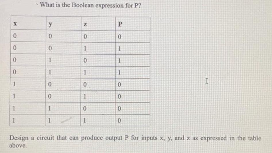
What is the Boolean expression for P? y 0. 1 1. 0. 1 1 1 0. 1. 1 1 Design a circuit that can produce output P for inputs x, y, and z as expressed in the table above. P.


Q: Question 8: In the sequential circuit shown below, if the initial value of the output QiQo is 00,…
A:
Q: write code in verilog How do I design a circuit with 8 inputs to detect and display the number of…
A: The digital circuit is given in the other step :
Q: Given the expression below, implement the equivalent circuit. X = ABC + ABC + AB Y = ABC + AB + BC…
A: HI THEREI AM ADDING ANSWER BELOWPLEASE GO THROUGH IT THANK YOU
Q: mbinational circuit has 3 inputs A, B, C and output F (A,B,C). F is true when (A is False and B is…
A: combinational circuit has 3 inputs A, B, C and output F (A,B,C). F is true when (A is False and B is…
Q: الم ملكة العربية السعودية وزارة التعليم العالي KINGDOM OF SAUDI ARABIA Ministry of Higher Education…
A: A magnitude digital Comparator is a combinational circuit that compares two digital or binary…
Q: We want to design a combinational circuit that computes the function: F(x) = 4r +1 r <3 2-1 r23…
A:
Q: Refer to the circuit diagram shown below. What is the expression for T3? * A T. B TA T₂ 2 с T. 5 T3…
A: From the given circuit diagram T3 is connected to OR gate and input of OR gate is 'C' and 'D' T3 =…
Q: Consider the below sequential circuit. Q clk Y What is the value of A(t+1) if X-1, Y=1, and A = 0?…
A: Here in this question we have given a JK flip flop.input to this JK flip flop are given by NOR…
Q: Given the expression below, implement the equivalent circuit. X = ABC + ABC + AB Y = ABC + AB + BC…
A: draw truth table draw circuit diagram of giiven expression
Q: Question1: What is the output of the following circuit: * A > B D- C > A=1 B=0 C=1 A=0 B=0 C=0
A: We are going to find out the output of given logic circuit with given input values of A, B and C.
Q: Based on the given circuit, what are the values of J and K, when A=1, B=1, C=1? 4 to 1 MUX C' J…
A: Need to find the value of J and K, for the given circuit : When J gets input from 4:1 MUX and K…
Q: Siven the following circuit and assuming that =1, B=0, C=1, what are the values of sum, arry, and Y…
A: Here A=1 and B=0 , this means input I2 will be available at the output Y.
Q: Write a MATLAB code to simulate the series RLC circuit and plot the voltage across the capacitor Vo…
A: R = 465.96; L = 0.1; C =0.00000001; G = tf([1/(R*C) 0],[1 1/(R*C) 1/(L*C)]); #tf mean transfer…
Q: We want to design a circuit that counts the number of 1s present on 3 binary inputs a, b, c and…
A: A) Truth table a b c y z 0 0 0 0 0 0 0 1 0 1 0 1 0 0 1 0 1 1 1 0 1 0 0 0 1 1 0 1 1 0…
Q: The OR gate operation can also be expressed by a Boolean Algebra equation. For the two input OR gate…
A: 46) Given : boolean equation: X = A+B+C Or operator is used in this Equation: A+B: is 0, When both A…
Q: b d y2 f
A: The answer for the above given question is given below:
Q: Exercise: Assume the following State table Present Next State Output x=1 State x=0 x=1 x=0 d f e a 1…
A: 1) The Corresponding circuit diagram:
Q: 3: Create a two-input one-output Multiple-Input Multiple-Output system of the form: y(s)-H;(s) u,(s)…
A: Most MPC applications involve plants with multiple inputs and outputs. You can use ss, tf, and zpk…
Q: Complete the following characteristic table for the circuit below: You need explain how you got the…
A: In this question, we have a synchronous sequential circuit. And we have some values at clock 't' and…
Q: Q1:For the following circuit find voltage gain, current gain input impedance ,output impedance…
A: Answer :-
Q: Which is the correct boolean expression for the logic circuit given below? А.B B А+ В. Y= ? A + C с…
A: Logic gates are the basic building blocks of any digital system. Some basic logic gates are AND…
Q: 2. Complete each circuit below by adding the needed devices so the output is high or low for all…
A: The solution for the given question is given below:
Q: What is the value at output O of the circuit below when x= 0, y=1?
A: The given diagram shows a logic circuit which is a combination of OR, AND and OR logic gates. The…
Q: 1. A(n) _______________ is a circuit that selects a single output value from a set of inputs based…
A:
Q: Suppose you have a circuit that implements the following truth table: Out 1 10 1 10 1 1 1 1 1 10 10…
A: Please check the step 2 for answer
Q: The next table represents a truth table of a 1-bit comparator. With 3 outputs. A. B A>B AB…
A: Actually, 1 byte= 8 bits.
Q: Make a truth table for logical circuits shown below A B Y = A B+AC A Y B C AC
A: By the given circuit diagram, one truth table is to be produced where three input variables are used…
Q: Digital engineer B. I. Nary has just completed the design of a sequential circuit which has the…
A:
Q: For the circuit shown below, if Is = 1A, the switch in the circuit has been closed for a long time…
A: Ans: 1200 A/Sec Let's solve it:
Q: This is the question: Suppose that we want to synthesize a circuit that has two switches x and y.…
A: Here in this synthesize circuit NOT AND and OR gate is used. So let us try to understand the figure…
Q: Write a handwritingreport including a short description about the circuit(including function,…
A: Answer is given below .
Q: We have a circuit that counts from 1 to 14. This circuit output (1,2,4,6,7) will light up red, when…
A: int pin1=11; int pin2=10; int pin3=9; int pin4=8; int timr=1000; int i=0; void setup() {…
Q: Program a circuit where a yellow LED light will turn on when a button is pressed 4 times and remain…
A: The function of an LED in a switch: LEDs (Light Emitting Diode ( led) transform electric power…
Q: Given the expression below, implement the equivalent circuit. X = ABC + ABC + AB Y = ABC + AB + BC…
A: For the given two expressions, we will draw their circuit and then we will make circuit table for…
Q: A B C D PO PO POD 1 L D E E F D G b. D PO B F G PO 1. Simulate the circuit and built the truth table…
A: Dear learner, hope you are doing well, I will try my best to answer this question. Thank You!!
Q: Based on the circuit shown below, answer the following questions: A B C Y a) Write the Boolean…
A: As per our guidelines we are supposed to answer only one question kindly repost other question as a…
Q: What does the value on the wire X do? That is, what is the difference in the output of this circuit…
A: Attached Handwritten solution image 01:
Q: From the circuit below : A- B- Cin Cout a. From the input signal A,B,Cin draw the output signal S…
A: The given circuit is full adder circuit. The truth table of full adder circuit is as below:…
Q: Consider the below given combinational circuit: 10 Il 4X1 MUX F Dan 12 13 A D в с What will be the…
A: Introduction : Given , A Circuit Diagram Having Gates and MuxWe have to find the function F , if D=1…
Q: Exercise 2: Determine the output F1 (X, Y, Z) and F2 (X, Y, Z) of the below circuit: 1 4 x 1 MUX 1-…
A: In this question, we are given 2 mux whose output is connected to a half adder. Logic: we will first…
Q: For the circuit shown below the output F is given by X- F O F = 1 O F = 0 O F = X O F = M|
A: Explanation : At, first Xor gate X and X are entered so, 0 will come out. At, Second Xor gate X…
Q: Explain the function of the circuit specified by the following HDL description: module 1 (A, B, S,…
A:
Q: if x, y, and z are three inputs of a full adders. the summation is given by : Select one: O a. OR…
A: Summation of full adder is XOR(x,y,z) Option d.XOR(x,y,z) is answer
Q: Here's a table showing the tco and teo for each of the components in the circuit bellow. Please…
A: Answer: In the given circuit we have one 2 input AND gate one 2 input XOR gate one 2 input MUX gate…
Q: c) Express the output column of the table below as a function of P, Q and R. Hence, design a circuit…
A: Here, we are going to draw the logic circuit for the given output. First we will find out the…
Q: CONSTRUCT Truth table for the circuit shown below: D. a b' d' Write Boolean expression for:…
A:
Q: There are only two states: "siren off" and "siren on" • There is one combinational output: 0 -…
A: According to the question: to design a car security system that operates as follows: Cases are given…
Q: For the following circuit, write a code on TinkerCAD to turn on the LED light when the push-button…
A: Turn on the led ligh when push button is pressed
Q: The next table represents a truth table of a 1-bit comparator. With 3 outputs. A>B AB Comparator B…
A: Actually, 1 byte=8 bits.
Q: Inputs Present Next State Next State State (PS) (NS) (NS) Output 9. 42 93 92 42 1 93 1
A: the Answer is


Trending now
This is a popular solution!

Step by step
Solved in 2 steps with 2 images


- Can u create a multiplier circuit for just P3, P4 and P5Given five inputs (a, b, c, d, e) connected to 8051’s port P1 and P2 with : P1.0 = a, P2.0 = b, P1.3 = c, P2.7 = d et P1.6 = e. Outputs S0 and S1 are connected to P3.0 and P3.1 respectively as shown in the figure below. We propose to realize the following logic S0 = a.b + c.d + e.(a.b + a.b) S1 = c.b + d + e.a.bBuild a circuit that takes four bits as input: W, X, Y, Z. Treat WX as a 2-bit unsigned binary number, and treat YZ as a second 2-bit unsigned binary number. Your circuit should generate the output corresponding to the product of WX and YZ. You will need 4 bits of output for this problem.For example, if your input was 1011, your inputs correspond to 2 and 3. That product is 6, so your output will be 0110.Create a truth table for this problem, show all k-maps and minimizations, and build the corresponding (minimized) circuit. Use XOR, XNOR, NAND, and NOR as appropriate if it reduces the number of gates used.
- Using Verilog continuous assignments or VHDL signal assignments, write a description of the circuit specified by the following Boolean functions: Out_1=(A+B′)C′(C+D)Out_2=(C′D+BCD+CD′)(A′+B)Out_2= (AB+C)D+B′CWrite a testbench and simulate the circuit’s behavior.What is F in SOP in expression F(w,x ,y z) = Σ(2, 4, 6, 8, 10, 12): d(0, 1, 3, 5, 7, 9, 11, 13, 14, 15) a. 1 b. F = (wx) + (yz) c. F = (xyz) + (wz) + (yz) d. F = (wy) + (xz)This question only reads: Build a decoder circuit. (Generic decoder?) What does this circuit do? If you added one more input, how many outputs would you need? How would a decoder be used?
- Write a Verilog code for any one of the combinational arithmetic Circuits, which are having minimum of three variables using any type of Modeling.This is the question: Suppose that we want to synthesize a circuit that has two switches x and y. The required functional behavior of the circuit is that the output must be equal to 0 if switch x is opened (x=0 ) and y is closed (y=1); otherwise the output must be 1. My friend sent me the answer which I will attach but I have no idea what is going on .. can someone please explain in detail?Write an OCTAVE program to plot the signal given below. P= Pmax sin(2πft); where Pmax = 10 MW, f=60 Hz. Find out time period and verify it with graph. Assume necessary data.
- you are going to implement finite state machine for traffic light 4way 6 input ( c1,c2,c3,c4, S and L) C1,C2,C3,C4 are sensors and s=1 sec L=25sec ,T to activate the timerWrite a program to plot the signal given below. P= Pmax sin(2πft); where Pmax = 10 MW, f=60 Hz. Find out time period and verify it with graph. Assume necessary data.Implement a combinational circuit with three inputs x, y, and z and three outputs A, B, and C.When the binary input is equal to 0, 1, 2 or 3, then the output is equal to the input + 1.When the binary input is 4, 5, 6 or 7 then the binary output is equal to the input – 2.