Make a truth table for logical circuits shown below A B Y = A B+AC A Y B C AC
Q: Design a combinational logic circuit that takes a 3–bit input and has one output P. The P output…
A:
Q: Question 8: In the sequential circuit shown below, if the initial value of the output QiQo is 00,…
A:
Q: Draw the block & logic diagram of a one-bit cell circuit
A: Block diagram of a one-bit-cell circuit Logic diagram of a one-bit-cell circuit (using two NAND…
Q: Which of the following circuits are combinational logic circuits? (Mark all that apply.)
A: Correct options are: Decoder, Mux, Full Adder Decoder is a combinational circuit. It has n input and…
Q: Draw the NAND implementation of the current equation. Given the expression below, implement the…
A: The question is to write the truth table and implement the equations using NAND.
Q: Q3/ Design a logical circuit by using the truth table below A 1 T. 1.
A:
Q: Given the expression below, implement the equivalent circuit. X = ABC + ABC + AB Y = ABC + AB + BC…
A: draw truth table draw circuit diagram of giiven expression
Q: . Identify each of the following expressions as SOP, standard SOP, POS, or standard POS: (a) AB +…
A:
Q: Make a truth table for logical circuits shown below A B Y = A B+A C A Y B A AC
A: By the given circuit diagram, three basic gates are used: AND-Gate, OR-Gate, and NOT-Gate. Before…
Q: Based on the given circuit, what are the values of J and K, when A=1, B=1, C=1? 4 to 1 MUX C' J…
A: Need to find the value of J and K, for the given circuit : When J gets input from 4:1 MUX and K…
Q: Draw the logic circuit represented by the following expression: a) (A+ C)B) + (CD + Ã) + (BD) b) AB…
A:
Q: Draw a combinational circuit that would provide the following truth table: A B C X 0 0 0 0 0 0 1 1…
A: I have provided solution in step2
Q: How are sequential circuits different from combinational circuits?
A: Sequential Circuits vs Combinational Circuits: - S.No. Sequential Circuits Combinational Circuit…
Q: 5) For the circuit shown in the figure below, find Z. 14 MUX lo S B A) Z = A B@C C) Z = A BeC B) Z =…
A:
Q: * The canonical SOP form of F(A.B.C)=DA'+BC is القصة واحد 0.1.2.37 F(A, B, C) = 2.1347 F(A, B, C) =…
A: We are given a boolean function and we have to find out its sop form. We will solve it using k-map…
Q: Chose the correct answer for the output F and G of the following circuit ( Assume that A= 10101010,…
A: You can find the complete explanation in the below steps. See below steps:
Q: Design a circuit diagram for the following comparator system that takes three 3-bit binary numbers…
A: The answer to the following question:-
Q: A combinational circuit has 3 inputs A, B, C and output F. F is true for following input…
A: Answer :- Option A) F = A’ +BC
Q: A combinational logic circuit has inputs A, B, C, D and E. The output Y is given by: fΠ M(15,31)…
A: Y = Π M(15,31) 15 = 01111 31 = 11111 In POS form, 100 is written as 0+1+1 That is for 1 we take…
Q: For the diagram shown and list included select which item in the list represents area G. (enter…
A: According to the information given:- We have to define the correct item from the list.
Q: draw a circuit diagram for 8 bit right and left logical shifter. Sham is three bits. I want…
A: With the aid of reversible logic synthesis, we have carried out this circuit diagram which…
Q: Given two 8-bit unsigned numbers, A and B:Using MSI components (comparators, multiplexers) design a…
A: Comparators: A comparator circuit compares two voltages and outputs either a 1 or a 0 to indicate…
Q: Example: Design a 4-input (A,B,C,D) digital circuit that will give at its output (X) a logic 1 only…
A:
Q: 1. Fill the table below and determine the logical operation of the following circuit A B в
A: From the given circuit, Z=A'B+AB'
Q: Implement the digital circuit shown in figure below using VHDL. X 10 2:1 MUX → f y Q D Cik
A: A device, which is acting like a building block for digital circuits, called logical circuit. It…
Q: What is the Boolean expression for P? y 0. 1 1. 0. 1 1 1 0. 1. 1 1 Design a circuit that can produce…
A:
Q: Q1:bulid the circuit using the following boolean algebra expressions D=A+B+C, D=AC'+AB'+BC
A:
Q: The combinational circuit shown on the right performs arithmetic operations on three 4-bit integers,…
A: Check further steps for the answer :
Q: What is the current flow through R1, R2, and R3? R2 3 Ohm R2২3ohm 9 V R 3 Ohm R1 = 1A. R2 = 1A. R3 =…
A: by Ohms law V = IR V=9 R = 3+3 + 3 I = V/R = 9/9 =1A The Registers are in series so same current…
Q: Design domino circuit whose output is @ Y = À +5C (Ā + B + C)+ AB = A:B.C + AB = A (BT +8) 9) Y =…
A: Given:
Q: Computer Science Need a code to make an arduino send a ir signal when given a analog input..
A: IR sensors are highly susceptible to ambient light and the IR sensor on this sensor is suitably…
Q: 1. What are the other combinational circuits besides adder and subtractor? Briefly describe each.
A: There are many combinational circuits besides adder and subtractor: -> Multiplexers ->…
Q: Simplify these expressions into simplified SOP form: a) W=AA+AB'+A'BB°C b) X=(A'+B)'+(A+B) c)…
A: a) W=A.A+A.B'+A'B.B'C ⇒W=A+AB'+0 [Since, A.A=A and B.B'=0] ⇒W=A.(1+B') ⇒W=A.1…
Q: connected to 8051’s port P1 and P2 with : P1.0 = a, P2.0 = b, P1.3 = c, P2.7 = d et P1.6 = e.…
A: five inputs (a, b, c, d, e) connected to 8051’s port P1 and P2 with : P1.0 = a, P2.0 = b, P1.3 = c,…
Q: U1A A U3B B 7408N 7404N 2C U3C 7400N 7404N
A: Over here given a circuit and we have to find a bolean equation for this. Note that the part a) 's…
Q: Based on the given circuit, what are the values ?of J and K, when A=1, B=1, C=1 4 to 1 MUX C' J…
A: Following is the correct answer to your questions: j=1 k=1.
Q: 2) Design a 4-bit arithmetic circuit with two selection variables Sı and S2 that performs the…
A: Given The answer is given below.
Q: 1. In the shown digital circuit F is equal to: а. 0 b. 1 c. x +y y- So d. None of the above 4 x I…
A: We need to find the output function.
Q: Consider the below given combinational circuit: 10 Il 4X1 MUX F Dan 12 13 A D в с What will be the…
A: Introduction : Given , A Circuit Diagram Having Gates and MuxWe have to find the function F , if D=1…
Q: Identify that function generated by the logic circuit shown below: * :Dr A B D O F= A'B' + C + D OF=…
A:
Q: For the circuit shown below the output F is given by X- F O F = 1 O F = 0 O F = X O F = M|
A: Explanation : At, first Xor gate X and X are entered so, 0 will come out. At, Second Xor gate X…
Q: 6. Vx(Gx v Hx), Xy(Fy A Ky) Hx), Fa Gc e using first order logic
A: This comes under Theory of Computation. PL logic is not sufficient, so we required some more…
Q: Here's a table showing the tco and teo for each of the components in the circuit bellow. Please…
A: Answer: In the given circuit we have one 2 input AND gate one 2 input XOR gate one 2 input MUX gate…
Q: What do you understand by basic logic gate and universal logic gate? Clarify your answer with…
A: Basic Logic Gates. Everything advanced frameworks can be built by just three fundamental basic…
Q: Design a 4-bit Arithmetic Logic Unit with proper connections that shows the operation of Output and…
A: The arithmetic logic unit (ALU) is a union of a digital circuit that executes arithmetic…
Q: ? (O
A: Binary Adder The Add micro-operation necessitates the use of data registers and digital components…
Q: Explain me please step by step the answer is pc is 007 and ac 0077
A: PART A: PC register stands for Program Counter. The Program Counter register points to the memory…
Q: 1. In the shown digital circuit F is equal to: а. О b. 1 с. х +у d. None of the above y. So S1 4 x I…
A: We are given a mux with select lines and input. We are going to find out its output. Please refer to…
Q: Draw the circuit diagram of the following: 1. (АB+ С) 2. А'ВС+ АB'С+ АВС' +АВС 3. (АВCD+ E)E 4. АB'…
A: Digital circuits represent Boolean logic. The inputs are directed towards outputs using logic gates…
Q: Design a circuit that compares two 3-bit numbers A and B to check if they are equal and less than.…
A: Basically, a 3-bit comparator is designed to check if the number A is equal to B or not, also if…
Complete task from image
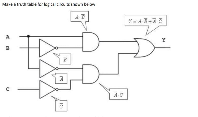
Step by step
Solved in 2 steps with 3 images
- Simplify the expression(A+B)(A'+B+C') such that the answer is: ( (B')(AC')' )'Using Verilog continuous assignments or VHDL signal assignments, write a description of the circuit specified by the following Boolean functions: Out_1=(A+B′)C′(C+D)Out_2=(C′D+BCD+CD′)(A′+B)Out_2= (AB+C)D+B′CWrite a testbench and simulate the circuit’s behavior.Please use algebraic manipulation and truth tables to find out whether or not the two circuits are equivalent.
- Apply De-Morgan’s theorem to the following expressions. (a) ((A+BC’)’+D(E+F’)’)’ (b) ((A+B+C)D)’ (c) (ABC+DEF)’ (d) (AB’+CD’+EF)’ Simplify the following Boolean algebraic expressions and draw a block diagram of the circuit for each simplified expression using AND OR and NOT gates. (a) AB’C’ + A’B’C’ + A’BC’ + A’B’C (b) A’BC + AB’C + A’BC + ABC’ + AB’C’ + A’BC’ + A’B’C’ (c) (A + B + C) (A + B’ + C’) (A + B + C’) (A + B’ + C)Write a truth table for F(abc) = (a+b)' (b+c')Design a circuit to implement the following truth table, where A and B are inputs and Z is the output. Give the Boolean equation that implements the circuit in the space provided. There may be more than one possible correct answer. You only need to list one possible correct answer. Input Output A B Z 0 0 1 0 1 0 1 0 1 1 1 1
- Use pencil and paper to solve this question. 1.. Construct a circuit for the following Boolean expressions : I. ( ~p V ~q) Λ (~p Λ r) Λ (q V~r) II. P∧∼Q) ∨(∼P∧R)Given the sequential circuit below, denote state A as 00, B as 01, C as 10, D as 11 and construct an implication table then complete the minimization process.Using the truth table below ( An example sum-of-products expression is (A+B+C)(A+B+C')(A+B'+C)(A'+B+C).) a. Write a product-of-sums Boolean expression bexp4 for the output ? of the truth table b. Draw a circuit that is a direct translation of bexp4 without any simplification. For the circuit, use a layout that is analogous to the layout of the sample circuit below (where the and and or gates are appropriately swapped).
- How does Binary adders work? (Our lesson is combination of logic circuit)Simplify this SOP and POS expression by Boolean laws : A’B’C + A’BC + AB’C’ + AB’C + ABC (A+B+C).(A+B’+C).(A’+B’+C’)I need explanintoin for these truth tables Output expression: Sum Pi=A⊕B Carry, Gi=AB Truth table: A B Sum Pi=A⊕B Carry, Gi=AB 0 0 0 0 0 1 1 0 1 0 1 0 1 1 0 1 The output expression of full adder circuit is Sum, S=A⊕B⊕Ci Carry, C0=Gi+CiPi=AB+CiA⊕B Truth table: A B Ci Sum, S=A⊕B⊕Ci Carry, C0=AB+CiA⊕B 0 0 0 0 0 0 0 1 1 0 0 1 0 1 0 0 1 1 0 1 1 0 0 1 0 1 0 1 0 1 1 1 0 0 1 1 1 1 1 1