What is the sequence of the operations if the limit switches, shown in Figure 5– 6, are used. What will happen in Figure 5–6 if limit switches are installed and the jumpers from terminals 6 and 7 to the coils are not removed?
What is the sequence of the operations if the limit switches, shown in Figure 5– 6, are used. What will happen in Figure 5–6 if limit switches are installed and the jumpers from terminals 6 and 7 to the coils are not removed?

Chapter21: Interlocking Methods For Reversing Control
Section: Chapter Questions
Problem 8SQ: What is the sequence of the operations if the limit switches, shown in Figure 216, are used. (Limit...

Related questions

Question
- What is the sequence of the operations if the limit switches, shown in Figure 5– 6, are used. What will happen in Figure 5–6 if limit switches are installed and the jumpers from terminals 6 and 7 to the coils are not removed?
Transcribed Image Text:L1 L2 L3
F
OL
OL
МOTOR
OL
Control
Transformer
Forward
Reverse
Stop
R
OL
F
R
R
(Source Delmar/Cangge Learning)
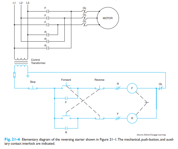
Fig. 21-6 Elementary diagram of the reversing starter shown in Figure 21–1.The mechanical, push-button, and auxil-
iary contact interlock are indicated.
Expert Solution
This question has been solved!
Explore an expertly crafted, step-by-step solution for a thorough understanding of key concepts.

This is a popular solution!

Trending now
This is a popular solution!

Step by step
Solved in 2 steps

Knowledge Booster


Learn more about
Need a deep-dive on the concept behind this application? Look no further. Learn more about this topic, electrical-engineering and related others by exploring similar questions and additional content below.Recommended textbooks for you