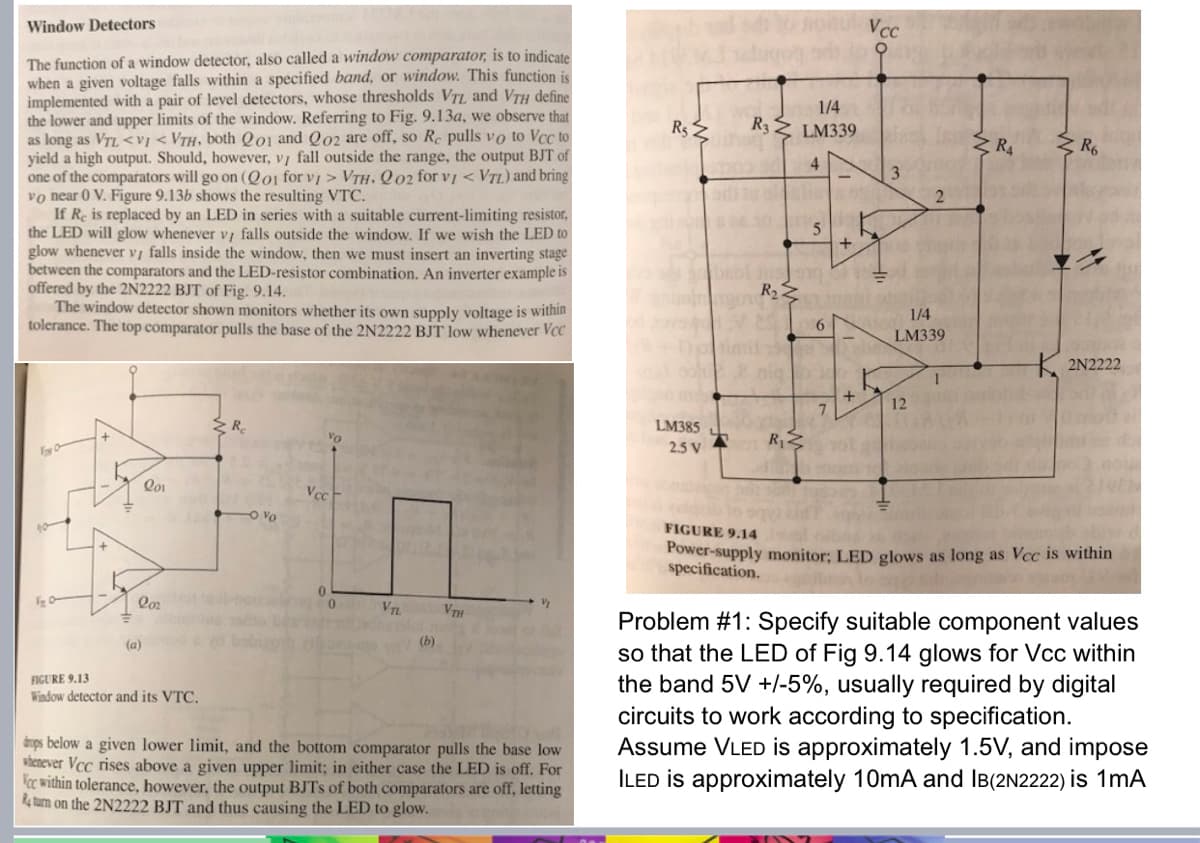
Window Detectors The function of a window detector, also called a window comparator, is to indicate when a given voltage falls within a specified band, or window. This function is implemented with a pair of level detectors, whose thresholds VTL, and VTH define the lower and upper limits of the window. Referring to Fig. 9.13a, we observe that as long as VTL VTH. Q02 for v1 < VTL) and bring vo near 0 V. Figure 9.13b shows the resulting VTC. If Re is replaced by an LED in series with a suitable current-limiting resistor, the LED will glow whenever vi falls outside the window. If we wish the LED to glow whenever vi falls inside the window, then we must insert an inverting stage between the comparators and the LED-resistor combination. An inverter example is offered by the 2N2222 BJT of Fig. 9.14. The window detector shown monitors whether its own supply voltage is within tolerance. The top comparator pulls the base of the 2N2222 BJT low whenever Voc
Window Detectors The function of a window detector, also called a window comparator, is to indicate when a given voltage falls within a specified band, or window. This function is implemented with a pair of level detectors, whose thresholds VTL, and VTH define the lower and upper limits of the window. Referring to Fig. 9.13a, we observe that as long as VTL VTH. Q02 for v1 < VTL) and bring vo near 0 V. Figure 9.13b shows the resulting VTC. If Re is replaced by an LED in series with a suitable current-limiting resistor, the LED will glow whenever vi falls outside the window. If we wish the LED to glow whenever vi falls inside the window, then we must insert an inverting stage between the comparators and the LED-resistor combination. An inverter example is offered by the 2N2222 BJT of Fig. 9.14. The window detector shown monitors whether its own supply voltage is within tolerance. The top comparator pulls the base of the 2N2222 BJT low whenever Voc

Introductory Circuit Analysis (13th Edition)
13th Edition
ISBN:9780133923605
Author:Robert L. Boylestad
Publisher:Robert L. Boylestad
Chapter1: Introduction
Section: Chapter Questions
Problem 1P: Visit your local library (at school or home) and describe the extent to which it provides literature...

Related questions
Question
Asap please
Transcribed Image Text:Window Detectors
The function of a window detector, also called a window comparator, is to indicate
when a given voltage falls within a specified band, or window. This function is
implemented with a pair of level detectors, whose thresholds VTL, and VTH define
the lower and upper limits of the window. Referring to Fig. 9.13a, we observe that
as long as VTL <VI < VTH, both Q01 and Q02 are off, so Re pulls vo to Vcc to
yield a high output. Should, however, vy fall outside the range, the output BJT of
one of the comparators will go on (Qo1 for VI > VTH. Q02 for v1 < VTL) and bring
vo near 0 V. Figure 9.13b shows the resulting VTC.
If Re is replaced by an LED in series with a suitable current-limiting resistor,
the LED will glow whenever v/ falls outside the window. If we wish the LED to
glow whenever v, falls inside the window, then we must insert an inverting stage
between the comparators and the LED-resistor combination. An inverter example is
offered by the 2N2222 BJT of Fig. 9.14.
The window detector shown monitors whether its own supply voltage is within
tolerance. The top comparator pulls the base of the 2N2222 BJT low whenever Vcc
O
Qo1
R
VO
Vec
1/4
Vcc
Rs
R,
R3
LM339
4
3
2
5
R₁₂
6
1/4
LM339
RA
R6
2N2222
1
+
7
12
LM385
2.5 V
R₁
0
10
202
VTL
VTH
(b)
(a)
FIGURE 9.13
Window detector and its VTC.
drops below a given lower limit, and the bottom comparator pulls the base low
whenever Vcc rises above a given upper limit; in either case the LED is off. For
Vec within tolerance, however, the output BJTS of both comparators are off, letting
Return on the 2N2222 BJT and thus causing the LED to glow.
FIGURE 9.14
Power-supply monitor; LED glows as long as Vcc is within
specification.
Problem #1: Specify suitable component values
so that the LED of Fig 9.14 glows for Vcc within
the band 5V +/-5%, usually required by digital
circuits to work according to specification.
Assume VLED is approximately 1.5V, and impose
ILED is approximately 10mA and IB(2N2222) is 1mA
Expert Solution
This question has been solved!
Explore an expertly crafted, step-by-step solution for a thorough understanding of key concepts.

This is a popular solution!

Trending now
This is a popular solution!

Step by step
Solved in 4 steps with 9 images

Knowledge Booster


Learn more about
Need a deep-dive on the concept behind this application? Look no further. Learn more about this topic, electrical-engineering and related others by exploring similar questions and additional content below.Recommended textbooks for you
Introductory Circuit Analysis (13th Edition)
Electrical Engineering
ISBN:
9780133923605
Author:
Robert L. Boylestad
Publisher:
PEARSON

Delmar's Standard Textbook Of Electricity
Electrical Engineering
ISBN:
9781337900348
Author:
Stephen L. Herman
Publisher:
Cengage Learning

Programmable Logic Controllers
Electrical Engineering
ISBN:
9780073373843
Author:
Frank D. Petruzella
Publisher:
McGraw-Hill Education
Introductory Circuit Analysis (13th Edition)
Electrical Engineering
ISBN:
9780133923605
Author:
Robert L. Boylestad
Publisher:
PEARSON
Delmar's Standard Textbook Of Electricity
Electrical Engineering
ISBN:
9781337900348
Author:
Stephen L. Herman
Publisher:
Cengage Learning
Programmable Logic Controllers
Electrical Engineering
ISBN:
9780073373843
Author:
Frank D. Petruzella
Publisher:
McGraw-Hill Education

Fundamentals of Electric Circuits
Electrical Engineering
ISBN:
9780078028229
Author:
Charles K Alexander, Matthew Sadiku
Publisher:
McGraw-Hill Education

Electric Circuits. (11th Edition)
Electrical Engineering
ISBN:
9780134746968
Author:
James W. Nilsson, Susan Riedel
Publisher:
PEARSON

Engineering Electromagnetics
Electrical Engineering
ISBN:
9780078028151
Author:
Hayt, William H. (william Hart), Jr, BUCK, John A.
Publisher:
Mcgraw-hill Education,