Wire BC has a diameter of 0.10 in. And its material has the stress-strain characteristics shown in the figure. Determine the vertical displacement of the handle D if the pull on the handle is slowly increased and reaches the magnitude of P = 655 lb. %3D
Wire BC has a diameter of 0.10 in. And its material has the stress-strain characteristics shown in the figure. Determine the vertical displacement of the handle D if the pull on the handle is slowly increased and reaches the magnitude of P = 655 lb. %3D

Steel Design (Activate Learning with these NEW titles from Engineering!)
6th Edition
ISBN:9781337094740
Author:Segui, William T.
Publisher:Segui, William T.
Chapter1: Introduction
Section: Chapter Questions
Problem 1.5.6P: The data in Table 1.5.3 were obtained from a tensile test of a metal specimen with a rectangular...

Related questions
Question
100%
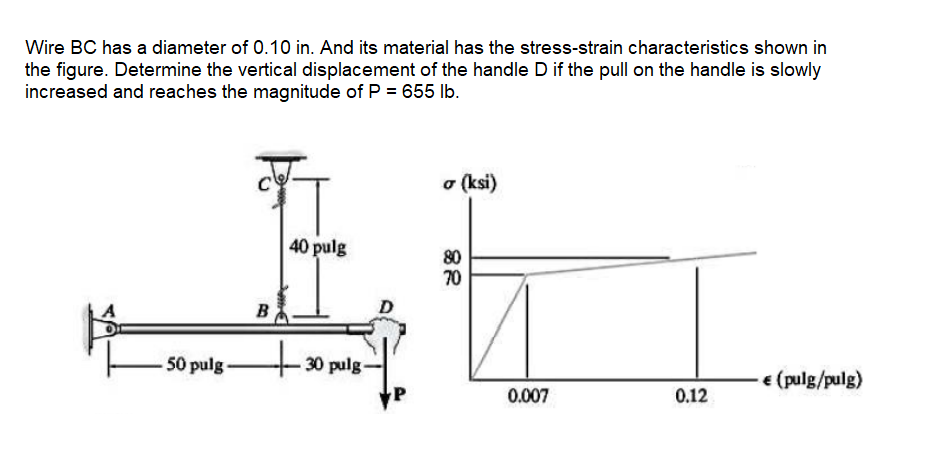
Transcribed Image Text:Wire BC has a diameter of 0.10 in. And its material has the stress-strain characteristics shown in
the figure. Determine the vertical displacement of the handle D if the pull on the handle is slowly
increased and reaches the magnitude of P = 655 lb.
o (ksi)
40 pulg
80
70
B
50 pulg -
30 pulg
€ (pulg/pulg)
0.007
0.12
Expert Solution
This question has been solved!
Explore an expertly crafted, step-by-step solution for a thorough understanding of key concepts.

Step by step
Solved in 2 steps

Recommended textbooks for you
Steel Design (Activate Learning with these NEW ti…
Civil Engineering
ISBN:
9781337094740
Author:
Segui, William T.
Publisher:
Cengage Learning
Steel Design (Activate Learning with these NEW ti…
Civil Engineering
ISBN:
9781337094740
Author:
Segui, William T.
Publisher:
Cengage Learning