1. Design a synchronous counter of three input (q1, q2, q3) using negative edge triggered T flip flop that goes through the following sequence figure 1. Show the design steps using excitation table of T flip-flop, circuit excitation table, K-map reduction and circuit diagram.
1. Design a synchronous counter of three input (q1, q2, q3) using negative edge triggered T flip flop that goes through the following sequence figure 1. Show the design steps using excitation table of T flip-flop, circuit excitation table, K-map reduction and circuit diagram.

Chapter22: Sequence Control
Section: Chapter Questions
Problem 6SQ: Draw a symbol for a solid-state logic element AND.

Related questions
Question
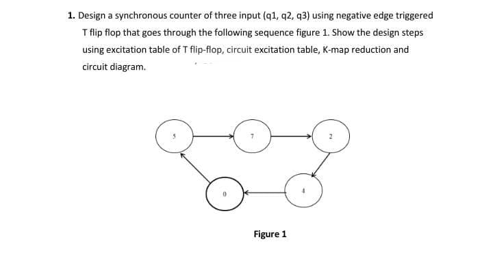
Transcribed Image Text:1. Design a synchronous counter of three input (q1, q2, q3) using negative edge triggered
T flip flop that goes through the following sequence figure 1. Show the design steps
using excitation table of T flip-flop, circuit excitation table, K-map reduction and
circuit diagram.
Figure 1
Expert Solution
This question has been solved!
Explore an expertly crafted, step-by-step solution for a thorough understanding of key concepts.

This is a popular solution!

Trending now
This is a popular solution!

Step by step
Solved in 4 steps with 4 images

Knowledge Booster


Learn more about
Need a deep-dive on the concept behind this application? Look no further. Learn more about this topic, electrical-engineering and related others by exploring similar questions and additional content below.Recommended textbooks for you