1.2 m A 0.9 m B 0.9 m D P Figure 1 The structure shown in Figure 1 is used to suspend heavy items. The structure is composed by four main members: The cable holding the load P, the pulley C, the beam ABC, and the solid, circular, A-36 steel¹ link DB. The structure is assembled using four 40 mm diameter A-36 steel pins (i.e. A, B, C and D) that work in single shear. The cable has a breaking load of 100 kN and the link BD has a diameter of 50 mm. It has already been established that the beam ABC can safely resist a load P = 150 kN. By analyzing all remaining possible failure modes you are required to establish the safe working load Pswl for this structure. Neglect the self-weight and use a F.S. = 2 in the calculation of all structural members.
1.2 m A 0.9 m B 0.9 m D P Figure 1 The structure shown in Figure 1 is used to suspend heavy items. The structure is composed by four main members: The cable holding the load P, the pulley C, the beam ABC, and the solid, circular, A-36 steel¹ link DB. The structure is assembled using four 40 mm diameter A-36 steel pins (i.e. A, B, C and D) that work in single shear. The cable has a breaking load of 100 kN and the link BD has a diameter of 50 mm. It has already been established that the beam ABC can safely resist a load P = 150 kN. By analyzing all remaining possible failure modes you are required to establish the safe working load Pswl for this structure. Neglect the self-weight and use a F.S. = 2 in the calculation of all structural members.

Mechanics of Materials (MindTap Course List)
9th Edition
ISBN:9781337093347
Author:Barry J. Goodno, James M. Gere
Publisher:Barry J. Goodno, James M. Gere
Chapter11: Columns
Section: Chapter Questions
Problem 11.2.10P: The figure shows an idealized structure consisting of rigid bars ABC And DEF joined by a linearly...

Related questions

Question
Transcribed Image Text:1.2 m
A
0.9 m
B
0.9 m-
112 mm
D
P
Figure 1
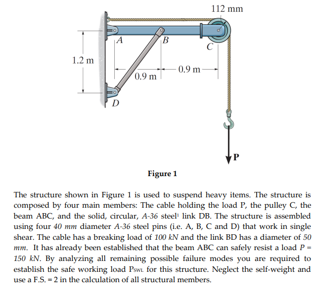
The structure shown in Figure 1 is used to suspend heavy items. The structure is
composed by four main members: The cable holding the load P, the pulley C, the
beam ABC, and the solid, circular, A-36 steel¹ link DB. The structure is assembled
using four 40 mm diameter A-36 steel pins (i.e. A, B, C and D) that work in single
shear. The cable has a breaking load of 100 kN and the link BD has a diameter of 50
mm. It has already been established that the beam ABC can safely resist a load P =
150 kN. By analyzing all remaining possible failure modes you are required to
establish the safe working load Psw for this structure. Neglect the self-weight and
use a F.S. = 2 in the calculation of all structural members.
Expert Solution
This question has been solved!
Explore an expertly crafted, step-by-step solution for a thorough understanding of key concepts.

Step by step
Solved in 2 steps with 2 images

Knowledge Booster


Learn more about
Need a deep-dive on the concept behind this application? Look no further. Learn more about this topic, mechanical-engineering and related others by exploring similar questions and additional content below.Recommended textbooks for you
Mechanics of Materials (MindTap Course List)
Mechanical Engineering
ISBN:
9781337093347
Author:
Barry J. Goodno, James M. Gere
Publisher:
Cengage Learning
Mechanics of Materials (MindTap Course List)
Mechanical Engineering
ISBN:
9781337093347
Author:
Barry J. Goodno, James M. Gere
Publisher:
Cengage Learning