111. For the truss shown in Fig. P-111, calculate the stresses in members CE, DE, and area of each member is 1.8 in.2. Indicate tension (T) or DF. The cross-sectional compression (C). OCE = 9260 psi (T); DE = 22.2 ksi (T); DF = 18.5 ksi (C) 8 ft Figure P-111 B Ans. 6 ft C 8 ft D 6 ft 8 ft E 30 kips
111. For the truss shown in Fig. P-111, calculate the stresses in members CE, DE, and area of each member is 1.8 in.2. Indicate tension (T) or DF. The cross-sectional compression (C). OCE = 9260 psi (T); DE = 22.2 ksi (T); DF = 18.5 ksi (C) 8 ft Figure P-111 B Ans. 6 ft C 8 ft D 6 ft 8 ft E 30 kips

Chapter4: Plane And Space Trusses
Section: Chapter Questions
Problem 32P

Related questions

Question
Using method of joint
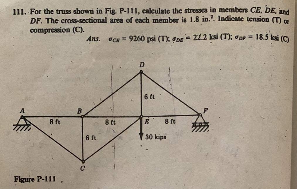
Transcribed Image Text:111. For the truss shown in Fig. P-111, calculate the stresses in members CE, DE, and
DF. The cross-sectional area of each member is 1.8 in.2. Indicate tension (T) or
compression (C).
OCE = 9260 psi (T); DE = 22.2 ksi (T); DF = 18.5 ksi (C)
8 ft
Figure P-111
B
Ans.
6 ft
C
8 ft
D
6 ft
8 ft
E
30 kips
Expert Solution
This question has been solved!
Explore an expertly crafted, step-by-step solution for a thorough understanding of key concepts.

Step by step
Solved in 4 steps with 4 images

Knowledge Booster


Learn more about
Need a deep-dive on the concept behind this application? Look no further. Learn more about this topic, civil-engineering and related others by exploring similar questions and additional content below.Recommended textbooks for you