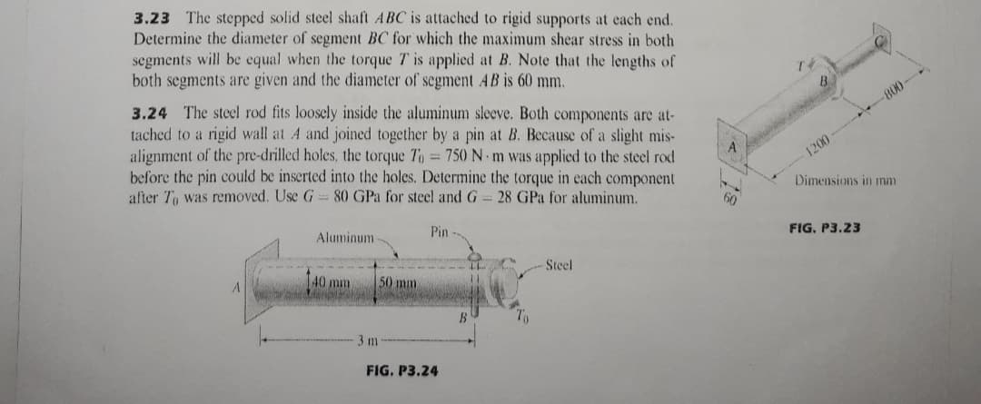
3.23 The stepped solid steel shaft ABC is attached to rigid supports at each end. Determine the diameter of segment BC for which the maximum shear stress in both segments will be equal when the torque T is applied at B. Note that the lengths of both segments are given and the diameter of segment AB is 60 mm. 3.24 The steel rod fits loosely inside the aluminum sleeve. Both components are at- tached to a rigid wall at A and joined together by a pin at B. Because of a slight mis- alignment of the pre-drilled holes, the torque To 750 N m was applied to the steel rod before the pin could be inserted into the holes. Determine the torque in each component after To was removed. Use G 80 GPa for steel and G 28 GPa for aluminum. -800- %3D 1200 Dimensions in mm Aluminum Pin FIG. P3.23
3.23 The stepped solid steel shaft ABC is attached to rigid supports at each end. Determine the diameter of segment BC for which the maximum shear stress in both segments will be equal when the torque T is applied at B. Note that the lengths of both segments are given and the diameter of segment AB is 60 mm. 3.24 The steel rod fits loosely inside the aluminum sleeve. Both components are at- tached to a rigid wall at A and joined together by a pin at B. Because of a slight mis- alignment of the pre-drilled holes, the torque To 750 N m was applied to the steel rod before the pin could be inserted into the holes. Determine the torque in each component after To was removed. Use G 80 GPa for steel and G 28 GPa for aluminum. -800- %3D 1200 Dimensions in mm Aluminum Pin FIG. P3.23

Elements Of Electromagnetics
7th Edition
ISBN:9780190698614
Author:Sadiku, Matthew N. O.
Publisher:Sadiku, Matthew N. O.
ChapterMA: Math Assessment
Section: Chapter Questions
Problem 1.1MA

Related questions

Question
PLEASE ANSWER NUMBER 3.23 MECH 221: PLEASE GIVE DETAILED SOLUTIONS AND CORRECT ANSWERS. I WILL REPORT TO BARTLEBY THOSE TUTORS WHO WILL GIVE INCORRECT ANSWERS.
Transcribed Image Text:3.23 The stepped solid steel shaft ABC is attached to rigid supports at each end.
Determine the diameter of segment BC for which the maximum shear stress in both
segments will be equal when the torque T is applied at B. Note that the lengths of
both segments are given and the diameter of segment AB is 60 mm.
3.24 The steel rod fits loosely inside the aluminum sleeve. Both components are at-
tached to a rigid wall at A and joined together by a pin at B. Because of a slight mis-
alignment of the pre-drilled holes, the torque To 750 N m was applied to the steel rod
before the pin could be inserted into the holes. Determine the torque in each component
after To was removed. Use G
800-
1200
80 GPa for steel and G 28 GPa for aluminum.
Dimensions in mm
Aluminum
Pin
FIG, P3.23
40 mm
50 mm
Steel
B
3 m
FIG. P3.24
Expert Solution
This question has been solved!
Explore an expertly crafted, step-by-step solution for a thorough understanding of key concepts.

Step by step
Solved in 2 steps

Knowledge Booster


Learn more about
Need a deep-dive on the concept behind this application? Look no further. Learn more about this topic, mechanical-engineering and related others by exploring similar questions and additional content below.Recommended textbooks for you
Elements Of Electromagnetics
Mechanical Engineering
ISBN:
9780190698614
Author:
Sadiku, Matthew N. O.
Publisher:
Oxford University Press

Mechanics of Materials (10th Edition)
Mechanical Engineering
ISBN:
9780134319650
Author:
Russell C. Hibbeler
Publisher:
PEARSON

Thermodynamics: An Engineering Approach
Mechanical Engineering
ISBN:
9781259822674
Author:
Yunus A. Cengel Dr., Michael A. Boles
Publisher:
McGraw-Hill Education
Elements Of Electromagnetics
Mechanical Engineering
ISBN:
9780190698614
Author:
Sadiku, Matthew N. O.
Publisher:
Oxford University Press
Mechanics of Materials (10th Edition)
Mechanical Engineering
ISBN:
9780134319650
Author:
Russell C. Hibbeler
Publisher:
PEARSON
Thermodynamics: An Engineering Approach
Mechanical Engineering
ISBN:
9781259822674
Author:
Yunus A. Cengel Dr., Michael A. Boles
Publisher:
McGraw-Hill Education

Control Systems Engineering
Mechanical Engineering
ISBN:
9781118170519
Author:
Norman S. Nise
Publisher:
WILEY

Mechanics of Materials (MindTap Course List)
Mechanical Engineering
ISBN:
9781337093347
Author:
Barry J. Goodno, James M. Gere
Publisher:
Cengage Learning

Engineering Mechanics: Statics
Mechanical Engineering
ISBN:
9781118807330
Author:
James L. Meriam, L. G. Kraige, J. N. Bolton
Publisher:
WILEY