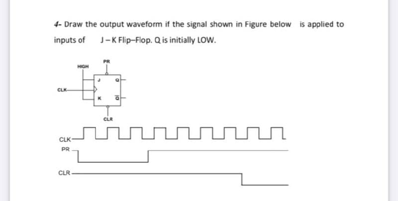
4- Draw the output waveform if the signal shown in Figure below is applied to inputs of J-K Flip-Flop. Q is initially LOW. HIGH CLK- CLK- PR CLR


Q: Design NOR base SR Flip flop in logic.ly website. Take a screenshot of the circuit and also create a…
A:
Q: Q6/ Design 4 bits up - down counter. Using JK-flip flop.
A: 4bit up-down counter
Q: Two edge-triggered J-K flip-flops are shown in figure below. If the inputs are as shown, draw the Q…
A: For J - K flip flopJKQn+1ooQno101o111Qn
Q: Create the circuit drawing. Clearly label all inputs and outputs.
A:
Q: i for the D and CLK inputs in Figure Determine the Q that the positive edge-triggered flip-flop is…
A: Latch is asynchronous device. It is level triggered device. It check input and change output…
Q: 4- Draw the output waveform if the signal shown in Figure below is applied to inputs of J-K…
A:
Q: Assume that there is a flip-flop with thecharacteristic given in Figure, where A and Bare the inputs…
A: Write the excitation table for the T flip-flop. Flip-flop input Previous state Next state…
Q: Q2: Draw Block diagram and the Q output from the waveform are applied to the S-R F.F with PRE and…
A:
Q: Design a 2-bit counter using D-Flip flops with one input. When the input is 0, the counter counts…
A:
Q: 5. The waveform in Figure Q5 are applied to the inputs of a J-K flip-flops (negative-edge…
A:
Q: output for the inputs in figure below Assume that Q starts LOW. 1) If the J-K flip-flop is positive…
A:
Q: What is meant by “a positive-edge flip-flop?”
A: NMOS: A transistor called an n-channel metal-oxide-semiconductor (NMOS) employs n-type dopants in…
Q: Assume that initially in Figure P9.7. Determine the values of A and B after one Clk pulse. Note that…
A:
Q: 2- Using JK Flip flops, a 2-bit counter will be designed that will count down ((11-10-01-00) when…
A: 1. The characteristic table of J-K flip flop is J K Qn+1 0 0 No change 0 1 0 1 0 1 1 1…
Q: Redesign the following flip flop circuit using SR flip flops only. Qnt JK K FF FF clk- clk T E
A: The solution is given below
Q: Can you find the logic circuit with 2 input using JK flip flop and D type flip flop?
A: taking states A= 00 B=01 C=10 D= 11
Q: In a J-K Flip Flop, if the input J=0 and K=1, then its output is.....
A:
Q: Solve both Draw state diagram of a J-K flip flop. write Verilog code for JK flip flop
A: Flip flop is a latch with additional control input (clock or enable ). A flip flop is used to store…
Q: For the input waveforms in figure below, determine the Q output if: 1) The J-K flip-flop is negative…
A:
Q: Figure 1 Explain the difference between D-Latch and D Q3: flip flop with the help of diagram? If the…
A: 3) The difference between D-latch and D Flip flop is as follows: D-Latch : A latch is an electronic…
Q: (a) Provide a block diagram and a function table for the D-type flip-flop with falling edge…
A: Since you have posted multiple questions, we will solve the first question for you. If you require…
Q: N Q(t) Q(t+1) X 1 1 Q(t) Q(t) 1 Q(t) Q(t) 1 1 X
A:
Q: 4) For the given waveforms determine the output Q and name the reasons for it. assume that the…
A: The given waveform is:
Q: Design a 2-bit binary counter using: One SR and one JK flip flop.
A: The counter circuit can be designed with the help of state transition table and k map.
Q: Q3/A/ The waveforms in Figure bellow are applied to the T-Flip Flop and clock inputs as Indicated,…
A:
Q: A Write the Boolean expression of the following Logic diagram. BC D= C' 11
A: Given data, Logic diagram
Q: Q1) Determine the Q and Q output waveforms of the (D flip-flops) in Figure below. Assume that the…
A:
Q: 2. Determine the Q waveform for the flip-flop as seen in the figure below. Assume that Q = 0…
A: In this question, We need to draw the output waveform of the JK filp flop. If initially Qn = 0
Q: Design asynchronous MOD-12 counter and draw the timing diagram for each flip-flop output. a.
A: “Since you have asked multiple questions, we will solve the first question for you. If you want any…
Q: 1- Design synchronous counter using negative edge D- type flip flop to count the following states :…
A:
Q: Determine the Q output waveforms of the flip-flop in Figure i for the D and CLK inputs in Figure…
A: Latch is asynchronous device. It is level triggered device. It check input and change output…
Q: Apply the waveforms shown below to a negative edge triggered D flip-flop and draw the Q waveform.…
A: To solve this problem one should know the truth table of D flip flop: When CLK is applied truth…
Q: Determine the output Q of a positive edge-triggered JK flip-flop for the input waveforms depicted in…
A:
Q: Define the following: flip-flops state table state diagram excitation table characteristic table…
A: Flip flop: It is one bit storage element and it can be synchronised with clock signal. Some of the…
Q: Q4(a) Determine the Q output waveform of the flip flop in the Figure Q4(a). Assuming that the…
A:
Q: show the waveforms for each flip-flop output with respect For the ring counter in Figure to the…
A: Truth table of the given ring counter Clock pulse Q0 Q1 Q2 Q3 Q4 Q5 Q6 Q7 Q8 Q9 0 1 0 0 0 0 0…
Q: 1- Design synchronous counter using negative edge D- type flip flop to count the following states :…
A:
Q: 4- Draw the output waveform if the signal shown in Figure below is applied to inputs of J-K…
A: Latch is asynchronous device. It is level triggered device. It check input and change output…
Q: a) Write the next-state equations for the flip-flops and the output equation. p) Construct the…
A:
Q: Q1: For the J-K flip-flop, determine the Q output for the inputs in figure below Assume that Q…
A:
Q: 2) For the given waveforms determine the output Q and name the reasons for it. assume that the…
A: The given waveform is Use the truth table for D Flip Flop,
Q: Figure Q1(c) shows a waveform of negative edge triggered T flip-flop. Determine tl output of Qo and…
A: A flip flop is used to store 1 bit of information to store series of data registers are used. T flip…
Q: 1- Design synchronous counter using negative edge D- type flip flop to count the following states…
A:
Q: Implementation of 8-bit Floating Light Digital Circuit Using JK Flip-Flop design it. (Hint: Using…
A: The implementation of the 8-bit floating light digital circuit using JK flip flop is shown below:
Q: Asm chart system given below in Hardwired hardware design structure with D flip flop design as.…
A: For the given algorithmic state machine, the state diagram can be drawn as follows:
Q: 4. Design an Octal Counter with D flip-flops. a) Draw the state diagram b) Draw the state table c)…
A: State Diagram,
Q: Glven a JK fiip-flop, describe thoroughly what the next state Is glven the different Inputs?
A: What is Master-Slave JK Flip Flop? The Master-Slave Flip-Flop is composed of two JK flip-flops…
Q: Q2/Design mod-5 synchronous counter using JK flip flop. Note/use the steps of design of synchronous…
A:
Q: 3. The waveforms shown in Figure below are applied to a negative edge-triggered JK flip- flop. The…
A: In this question, We need to draw the output waveform of the jK filp flop. We know the output of…
Q: 1) For the given waveforms determine the output Q and name the reasons for it. Assume that the Flip-…
A: The given waveform is:

Step by step
Solved in 2 steps with 1 images


- Compare the circuits, characteristic tables, and the timing diagrams of SR Flip-flops, JK flip-flops, and D flip flops. In your own words, describe the similarity and differences in behavior of these flip flops. Then go on to make comparison between Mealy and Moore machines, first describe each FSM and then elaborate on the similarity and differences between them.For the frequency divider circuit the D-flip-flop is a CD4013 Dual D-Type flip-flop V2 is a square wave applied to the Clock input and Q is the ouput waveform. a. What is the frequency of the square wave Clock from V29? b. What is the frequency of the output pin Q? c. How many D-flip-flops are implemented in the CD4013 Chip? d. How many outputs are implemented in each D-flip-flop? List them.Design the asynchronous counter circuit using JK flip-flops, starting from the smallest decimal digit to the largest decimal digit in the following numbers. (1180501624)
- Design a Mode 14 asynchronous forward counter circuit. (Use JK or T type flip-flops) I designed the mode 11 forward counter circuit below (using JK or T type flip-flop) Can you draw a Mod 14 asynchronous forward counter circuit as in the photo?Determine the Q waveform for the flip-flop as seen in the figure below. Assume that Q = 0 initially.Show the digital circuit diagram, output waveforms and truth table of a modulo-5 up counter using toggle flip-flops and explain the working principle.
- The waveforms shown are to be applied to a positive-edge triggered flip-flop- What is the value of output Q' at point X?a. highb. lowc. indeterminated. Transitioning from low to highe. Transitioning from high to lowDigital Logic Design Design a BCD ripple up counter using positive edge trigger J-K flip-flops.Design an Implementation of 8-bit Floating Light Digital Circuit Implementation Using D Flip-Flop. Interpret the results. (Hint: Using Shift Register)
- Complete the design process using full encoding and D-flip flop for the the function described by the follow state diagram and draw the schematics.Design a digital logic circuit using only NAND gates for the logic expressiongiven by: F=A.(B +C)Question Vv Design a synchronous counter using a J-K Flip-flop with an irregular binary count sequence shown in the state diagram.